


2-2
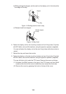
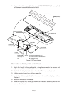
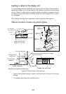
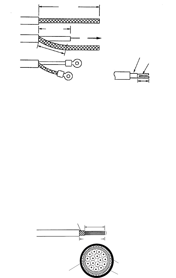
6. Ground the armor through the two washers as shown above. Trim the shields
considering their location on the earth terminal inside the scanner unit. Fit a
crimp-on lug (yellow, FV5.5-4, ø4) to inner and outer shields, then connect
them to the ground terminal inside the scanner unit.
7. Determine the length of each core considering its location on STB-1 in the
scanner unit (see the interconnection diagram on page S-1). Remove approx.
6 mm of the vinyl insulation from the end of each core and fix the crimp-on lug
FV1.25-M3 (Red) to each core.
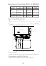
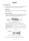
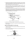
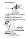
8. Remove the outer sheath of the coaxial cable (2C-2V) by 75 mm. Pull back the
braided shield to expose the inner core. Remove approx. 25 mm of insulator
from the end of inner core and fold back conductor as illustrated below. Shorten
the shield leaving approx. 45 mm. Fit crimp-on lugs to the conductor (FVD1.25-
3, Red) and braided shield (FV1.25-M3, Red).
Coaxial cable
2C-2V
50 mm
45 mm
Fold back the conductor
as illustrated below.
75 mm
Inner core
Conductor
6 mm
Crimp-on lug
FVD1.25-3
(Red, ∅3)
Crimp-on lug
FV1.25-M3
(Red, ∅3)
Figure 2-3 Fabrication of coaxial cable
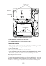
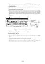
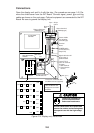
9. Lead cable into cable gland, tighten clamping gland and seal with putty.
10.Connect wiring to terminal STB-1 in the scanner unit referring to the intercon-
nection diagram.
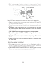
Signal cable 660V-MPYCY-16 (JIS cable)
1. Unfasten the clamping gland from the upper cable gland, and remove the gas-
ket and flat washers.
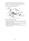
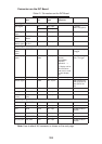
2. Shorten the cable as appropriate. Remove the vinyl sheath by 600 mm. Re-
move the armor by 590 mm.
Armor
Conductors
Armor
Vinyl sheath
Core
φ = 1.25 mm
2
600 mm
590 mm
Figure 2-4 Fabrication of signal cable 660V-MPYCY-16