


1-13
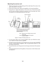
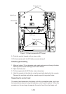
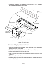
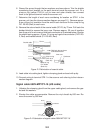
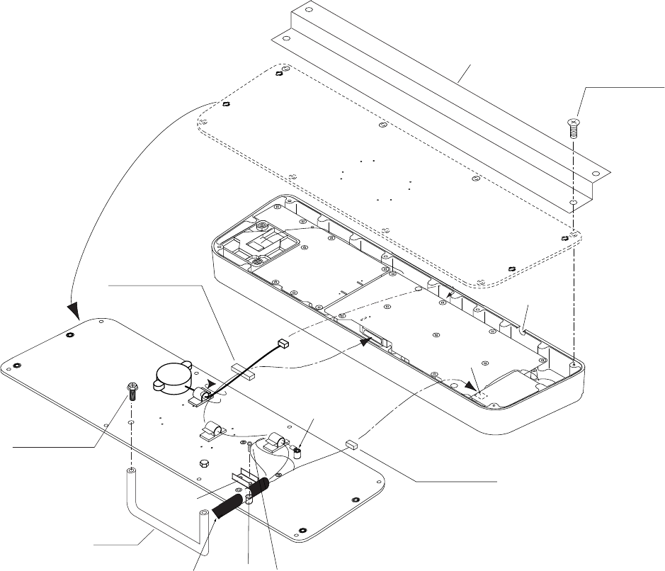
4. Replace the cable assy. with cable assy. UL2464SB2-0P/1P (10 m, supplied)
as below and reassemble the control head.
KB BOTTOM
PLATE
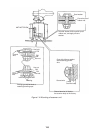
P312 FX Connector
P314 XH3P
J312 (underside)
J314 (underside)
Lay cable in slot.
Screw
M4X8 (8 pcs.)
Pan-head Screw M4X8 (2 pcs.)
Be careful not to pinch cable between
KB clamp and spacer.
Spacer
KB Clamp
Earth Wire
Upset Screw
M6X12 (2 pcs.)
Handle
Replace with
cable assy. in
kit.
J317 (underside)
KB Fixing Plate
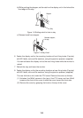
Figure 1-13 Control head
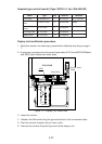
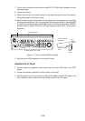
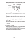
Connection of display unit to control head
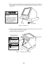
1. Attach the handle to the handle plate, using the screws for the handle and
bottom cover of the control head.
2. Attach the handle plate to location where the KB arms were fastened.
3. Pull the monitor toward you until you hear click.
4. Lead in the cable assy. (option) from the rear entrance of the display unit. See
Chapter 2.
5. Raise the monitor and fix the stay.
6. Inside the display unit, fasten ground wire of the cable assembly with an M4
screw on the chassis.