


2-3
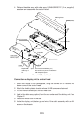
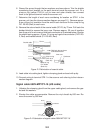
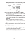
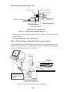
3. Slide the clamping gland, washers and gasket on the power cable. Fold back
the armor by 5 mm, then put it between washer and cable gland body as below.
Armor (folded back)
Gasket
Seal with putty
after tightening.
Vinyl sheath
Clamping gland
Flat
washer
Cable gland
Flat
washer
Flat
washer
Figure 2-5 Passing clamping gland, washers and gasket on the signal cable
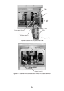
4. Determine the length of the cores considering their location on STB-2 and STB-
3. Trim conductors as necessary.
5. Ground the armor by inserting it through the two flat washers near the cable
gland.
6. Remove the sheath of each core by 6 mm. Fix crimp-on lugs (FV1.25-4, blue,
ø4) to each conductor. Make sure each connection is secure both electrically
and mechanically.
7. Lead cable into cable gland, tighten clamping gland and seal with putty.
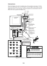
8. Connect the conductors to STB-2 and STB-3, referring to the interconnection
diagram on page S-1.
9. Check for loose screws and poor contact on crimp-on lugs. Close terminal
boards.
10.Grease the fixing bolts for the cover, gasket and tap holes in the scanner chas-
sis. Attach cover.
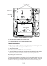
When the de-icer is installed
1) Before beginning any work on the scanner unit, turn off the breaker for the de-
icer line at the main switchboard to remove the power (100 VAC, 1ø) to the de-
icer. (Turning off the power to the display unit has no effect.)
2) The neck of the scanner unit becomes VERY HOT when the de-icer is working.
(The de-icer turns on when ambient temperature is below 0°C.)