


11GHP 10 Marine Autopilot System Installation Instructions
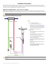
Electrical/Data Connection and Mounting Considerations
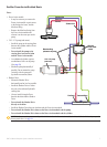
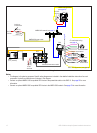
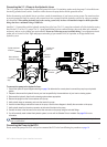
The GHP 10 components connect to each other and to power using the included cables. Ensure that the correct cables reach
each component, and that each component is in an acceptable location, before mounting any components. Read the following
considerations and consult the diagram on the next page before you begin installation.
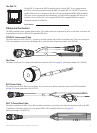
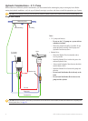
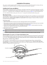
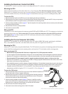
The Pump and the ECU
The pump must be located within 19 in. (0.5 m) of the ECU, mounted horizontally if possible. If you cannot mount the pump
horizontally, do not mount the pump vertically with the pump head (connectors) down.
The cables from the pump to the ECU cannot be extended.
The ECU power cable connects to the boat battery.
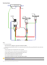
The CCU and the ECU
Do not mount the CCU or the ECU in a location where they will be submerged or exposed to wash-down.
Mount the CCU in the forward half of the boat, no higher than 10 ft. (3.05 m) above the waterline.
You can mount the CCU below the waterline, as long as it is not in a location where it will be submerged or exposed to wash-
down.
Mount the CCU bracket on a vertical surface or under a horizontal surface, so that the connected wires hang straight down.
Do not mount the CCU near magnetic material, magnets (speakers and electric motors), or high-current wires.
Mount the
CCU at least 24 in. (0.61 m) away from movable or changing magnetic disturbances such as anchors, anchor chain, wiper motors,
tool boxes, and the autopilot pump. Use a handheld compass to test for magnetic interference in the area.
The CCU/ECU interconnect cable connects the CCU to the ECU, and is 9
1
/
2
ft. (3 m) long. If you cannot mount the CCU within
9
1
/
2
ft. (3 m) of the ECU, extension cables are available in lengths of 16
1
/
2
ft. (5 m) and 49 ft. (15 m). (See page 4).
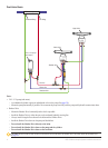
The CCU/ECU interconnect cable connects the CCU to the Shadow Drive, the alarm buzzer, the tachometer of the boat, and the
yellow CCU signal wire of the GHC 10 using wires with bare ends. See page 17 for wiring instructions and diagrams.
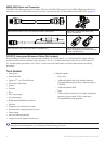
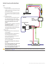
The CCU and the GHC 10
The CCU and the GHC 10 connect to a NMEA 2000 network. If you do not have a NMEA 2000 network on your boat, the
equipment necessary to build one is provided. For instructions on setting up the NMEA 2000 network, see page 21.
You can connect an optional NMEA 2000-compatible GPS device to the NMEA 2000 network to use waypoint and route data with
the GHP 10.
The GHC 10
Wire the GHC 10 to the battery of the boat and to the yellow CCU signal wire of the CCU/ECU interconnect cable.
If you do not have an optional NMEA 2000-compatible GPS device, you can wire an optional NMEA 0183-compatible GPS
device to the power/data cable of the GHC 10 instead (see page 23).
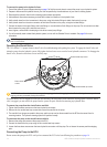
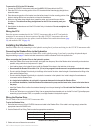
The Shadow Drive
Install the Shadow Drive closer to the helm than to the pump.
Mount the Shadow Drive horizontally, as level as possible.
Mount the Shadow Drive at least 12 in. (0.3 m) away from magnetic material such as speakers and electric motors,
including the autopilot pump.
•
•
•
•
•
•
•
•
•
•
•
•
•
•
•
•
•