


5GHP 10 Marine Autopilot System Installation Instructions
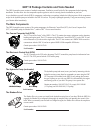
Installation Preparation
Before installing the GHP 10 autopilot system, it is important for you to completely understand where all the components will be
located on your boat. Temporarily place all the components where you plan to install them. Ensure that all cables and hydraulic hoses
can reach the necessary components before mounting any components.
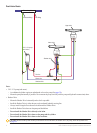
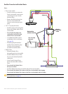
Hydraulic Considerations – 2.0 L and 1.2 L Pumps
Different boats have different hydraulic considerations you must examine before mounting the pump or cutting any hoses. Before
starting the hydraulic installation, verify the type of hydraulic steering in your boat, and where to install the appropriate type of pump.
CAUTION: If the hydraulic steering of your boat does not match the hydraulic layouts in this manual, contact Garmin Product Support.
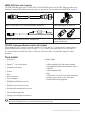
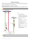
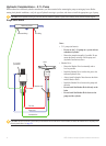
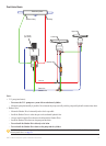
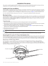
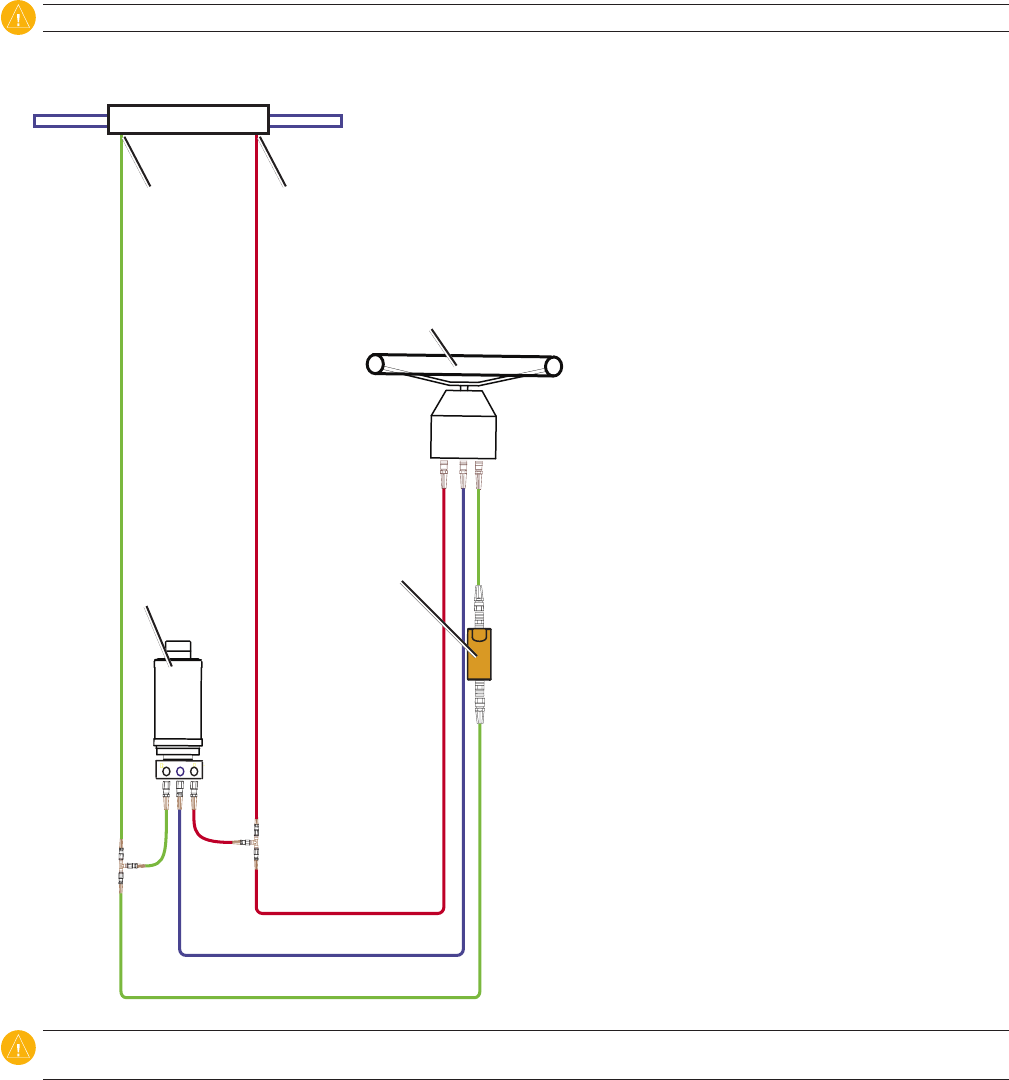
Single-Helm Boats (Without Power Assist)
Notes:
2.0 L/1.2 L pump (and motor):
An unbalanced cylinder requires an
unbalanced valve on the pump (See page 30)
Mount the pump horizontally if possible. Do
not mount the pump vertically with the pump
end (hydraulic connections) down.
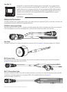
Shadow Drive
Mount the Shadow Drive horizontally and as
level as possible.
Install the Shadow Drive in either the port or
the starboard hydraulic steering line.
Always install a length of hose between the
helm and the Shadow Drive.
Do not install the Shadow Drive directly to
the helm.
Install the Shadow Drive between the pump
and the helm.
Do not install the Shadow Drive between
the pump and the cylinder.
•
◦
◦
•
◦
◦
◦
◦
◦
◦
Balanced cylinder
Port ttingStarboard tting
2.0 L/1.2 L pump
(and motor)
Port line
Return line
Starboard line
Shadow drive
Helm
P R S
CAUTION: Do not turn the system on until you bleed all the air from the helm, the Shadow Drive, the pump, and all the hydraulic lines.
See page 24.