


30 GHP 10 Marine Autopilot System Installation Instructions
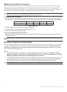
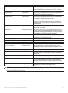
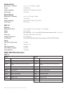
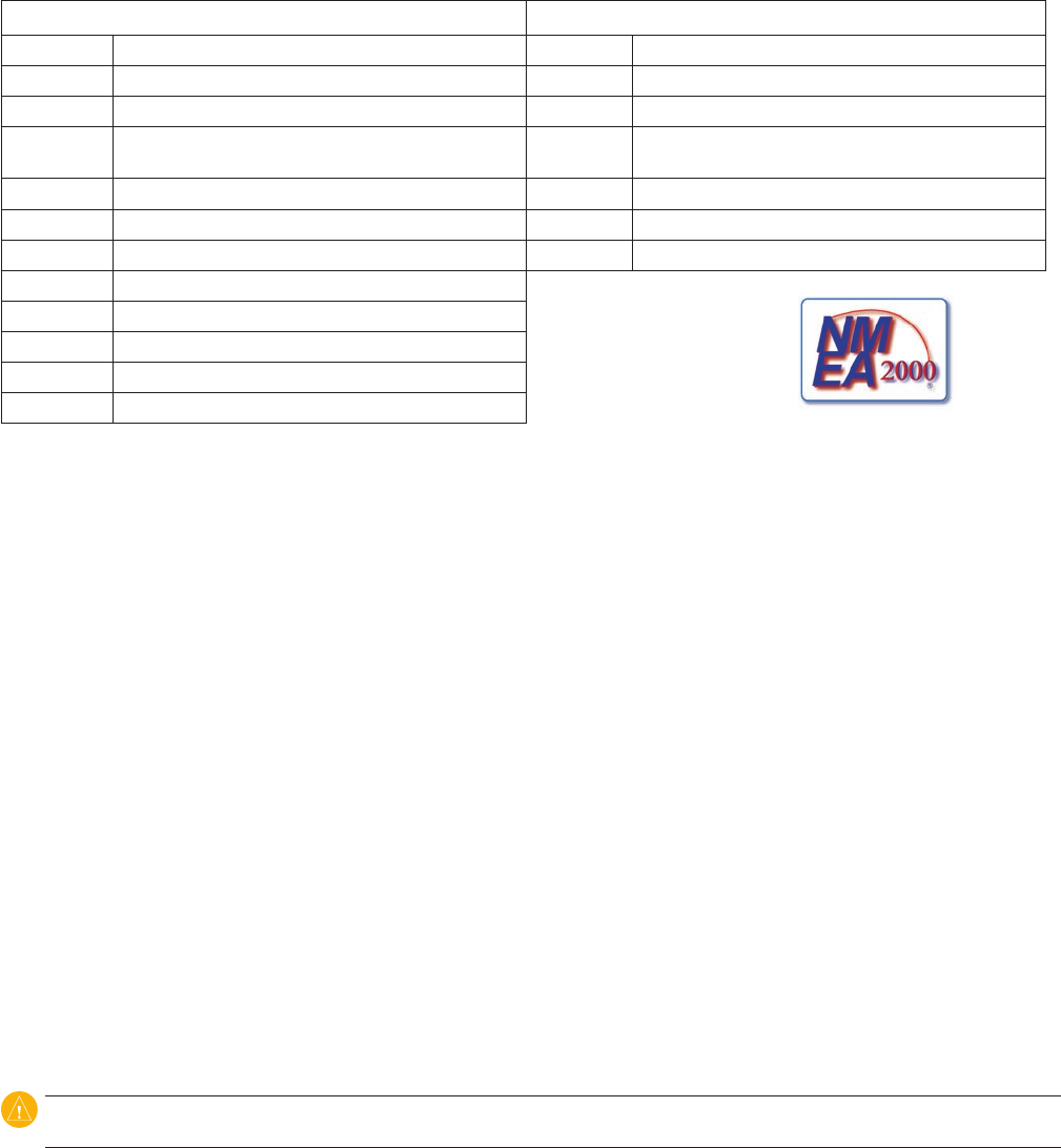
CCU
Receive Transmit
059392 ISO Acknowledgment 059392 ISO Acknowledgment
059904 ISO Request 059904 ISO Request
060928 ISO Address Claim 060928 ISO Address Claim
126208 NMEA - Command/Request/Acknowledge Group
Function
126208 NMEA - Command/Request/Acknowledge Group
Function
126464 Transmit/Receive PGN List Group Function 126464 Transmit/Receive PGN List Group Function
126996 Product Information 126996 Product Information
127258 Magnetic Variation 127250 Vessel Heading
127488 Engine Parameters - Rapid Update
129025 Position - Rapid Update
The GHP 10 and the GHC 10
are NMEA 2000 certied.
129026 COG & SOG - Rapid Update
129283 Cross Track Error
129284 Navigation Data
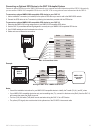
NMEA 0183 Information
The GHC 10, when connected to an optional NMEA 0183-compatible GPS device, uses the following NMEA 0183 sentences:
Receive—wpl, gga, grme, gsa, gsv, rmc, bod, bwc, dtm, gll, rmb, and xte.
Transmit
—hdg.
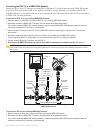
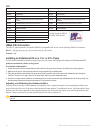
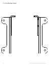
Installing an Unbalanced Kit on a 1.2 L or 2.0 L Pump
If your boat has an unbalanced cylinder steering system, then you need to install the optional unbalanced kit. Do not use a 2.1 L
pump on an unbalanced cylinder steering system.
To install the unbalanced kit:
1. Loosen and remove the four screws that hold the manifold to the pump body. Remove the manifold from the pump body.
2. Replace the O-rings on the pump body with the O-rings supplied in the unbalanced kit.
3. Place the unbalanced valve between the pump body and the manifold, with the O-rings on the unbalanced valve facing the
manifold. There are six O-rings—three on the pump body, and three on the unbalanced valve.
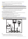
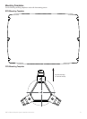
4. Use the four longer screws included in the unbalanced kit to connect the manifold and unbalanced valve to the pump body. Use
thread-locking compound and tighten the screws to 35 inch-pounds of torque.
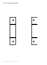
Adjusting and Calibrating the Unbalanced Valve
The brass screws on the sides of the unbalanced valve adjust the valve. Compare the amount of screw protruding beyond the valve
body on both sides of the valve. Both screws should protrude the same distance. To recalibrate the screws, fully tighten both of them
until they stop. Be sure they protrude the same distance after they stop. If not, loosen the shorter screw until they protrude the same
distance. Unscrew each screw by two and one-half full turns. The valve is ready for use.
CAUTION: Do not unscrew the brass screws more than the specied amount. Do not operate the system with the brass screws fully
tightened.