


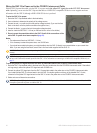
20 GHP 10 Marine Autopilot System Installation Instructions
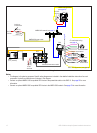
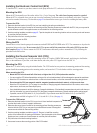
Wiring the GHC 10 to Power and to the CCU/ECU Interconnect Cable
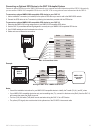
With the GHC 10 power/data cable, wire the GHC 10 to power and to the yellow CCU signal wire on the CCU/ECU interconnect
cable. Optionally, you can wire the GHC 10 power/data cable to a NMEA 0183-compatible GPS device to use waypoint and route
information with the GHP 10, although a NMEA 2000 GPS device is preferred.
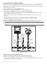
To wire the GHC 10 to power:
1. Route the GHC 10 power/data cable to the boat battery.
2. Use a voltmeter to determine the polarity of the voltage source.
3. Connect the red (+ or positive) wire to the positive voltage terminal. (If you use the fuse
block on the boat, route the positive connection through the fuse.)
4. Connect the black (- or ground) wire to the negative voltage terminal.
5. Install or check the AGC/3AG – 1 A fuse (on the fuse block or in the in-line holder).
6. Do not connect the power/data cable to the GHC 10 until all the connections of the
entire GHP 10 system have been completed (page 24).
Notes:
The replacement fuse is an AGC/3AG – 1 A fuse.
If it is necessary to extend the power wires, use 18 AWG wire.
If your boat has an electrical system, you might be able to wire the GHC 10 directly to an unused holder on your current fuse
block. If you are using the fuse block, remove the in-line fuse holder supplied with the GHC 10.
CAUTION: The GHC 10 maximum input voltage is 32 Vdc. Do not exceed this voltage, because this can damage the GHC 10 and void the
warranty.
NOTE: During a typical installation, use only the red, black, and yellow wires. The other wires are used for NMEA 0183 connections, and do
not have to be connected for normal operation of the GHC 10. For information on connecting to a NMEA 0183-compatible GPS device, see
page 23.
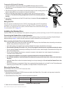
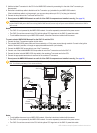
To wire the yellow CCU signal wire from the GHC 10 power/data cable to the CCU/ECU interconnect cable:
1. Route the GHC 10 power/data cable to the bare end of the color-coded wires from the CCU/ECU interconnect cable. If the cable is
not long enough, extend the yellow CCU signal wire with 22 AWG wire.
2. Connect the yellow CCU signal wire from the GHC 10 power/data cable to the yellow wire on the CCU/ECU interconnect cable.
If you install multiple GHC 10 units and want to turn the GHP 10 autopilot system on with any of the installed GHC 10 units,
connect all of the yellow CCU signal wires from the GHC 10 units to the yellow wire on the CCU/ECU interconnect cable.
3. Solder and cover all bare-wire connections.
NOTE: The yellow CCU signal wire must be connected from the GHC 10 power/data cable to the CCU/ECU interconnect cable, or the GHP
10 autopilot system will not power on with the GHC 10.
•
•
•
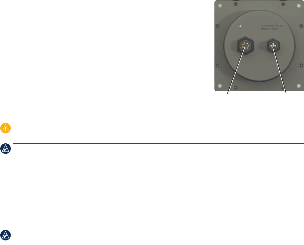
Power/data NMEA 2000Power/data NMEA 2000