


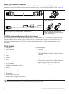
12 GHP 10 Marine Autopilot System Installation Instructions
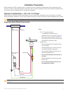
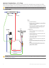
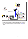
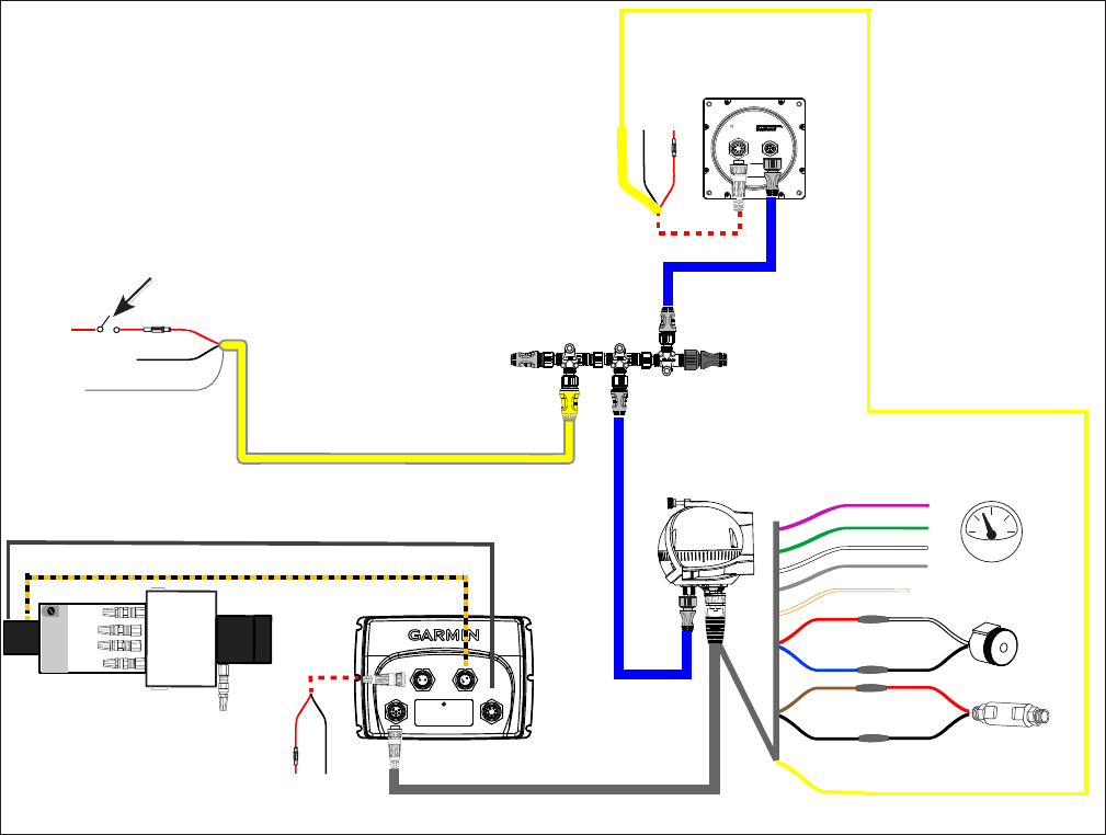
GHP 10 General Wiring Outline
ENCODER
CCU
POWER
}
PUMP
NMEA 2000 network (see page 21)
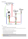
CCU
ECU
Pump
(2.1 L pictured)
GHC 10
Shadow Drive
Alarm buzzer
Boat tachometer
Yellow CCU signal wire (see page 20)
For CCU bare-wire connections, see page 17.
For tachometer wiring,
see page 18
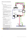
Orange - unconnected
Red (+)
White (+)
Red (+)
Blue (-)
Black (-)
Black (-)Black (-)
Brown (+)
Red (+)
Black (-)
12 Vdc
40 A fuse
NMEA 2000 power cable
9-16 Vdc
3 A fuse
Red (+)
Black (-)
Drain (-)
Ignition or
in-line switch
Black (-)
Red (+)
8-32 Vdc
1 A fuse
Yellow CCU signal wire
(see page 20)
CCU/ECU Interconnect cable
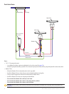
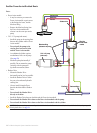
Notes:
This diagram is for planning purposes. Specic wiring diagrams are included in the detailed installation instructions for each
component. Hydraulic connections are not shown in this diagram.
Connect an optional NMEA 0183-compatible GPS device to the power/data cable on the GHC 10. See page 23 for more
information.
Connect an optional NMEA 2000-compatible GPS device to the NMEA 2000 network. See page 23 for more information.
•
•
•