


15GHP 10 Marine Autopilot System Installation Instructions
Connecting the 2.1 L Pump to the Hydraulic Lines
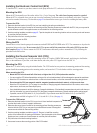
The 2.1 L pump must be isolated from the electrical ground of the boat. Use insulating washers under the pump if it is installed on an
electrically-grounded (metal) surface. Install the washers between the pump bracket and the grounded surface
Before disconnecting any hydraulic lines on your boat, consult the manufacturer of your boat or steering system. You must know how
to properly prepare the hoses for removal, and you must know how to properly bleed the hydraulic system of air when you complete
the connections. When adding hydraulic hose to the steering system, only use hose with machine-crimped or eld-replaceable
ttings that have a minimum rating of 1000 lb/in
2
.
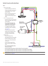
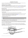
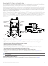
Install the 2.1 L pump inline with the hydraulic steering lines of the boat. The 2.1 L pump does not branch off of the hydraulic steering
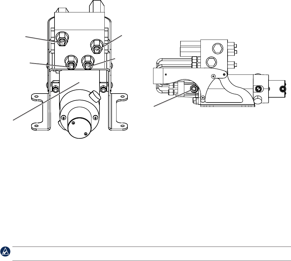
lines like the 2.0 L or the 1.2 L pumps. The 2.1 L pump manifold has ve hose-connector ttings, three to the helm (port, starboard,
and return), and two to the cylinder (port and starboard). Do not use Teon tape on any hydraulic tting. Use an appropriate thread
sealant such as Loctite Pro Lock Tight multipurpose anaerobic gel, part number 51604, or equivalent, on all pipe threads in the
hydraulic system.
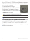
Pump/motor
body
Helm port
connector
Helm starboard
connector
Cylinder port
connector
Cylinder starboard
connector
Helm return-line
connector
To connect the pump to the hydraulic lines:
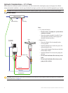
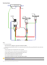
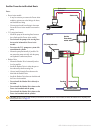
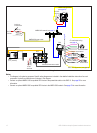
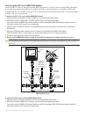
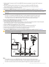
1. Consult the hydraulic layout diagrams starting on page 8 to determine the correct place to connect the pump to your hydraulic
system.
2. Prepare to disconnect the hydraulic lines in your boat as specied by the manufacturer of your boat or steering system.
3. Disconnect the hydraulic lines from the steering system where appropriate.
4. Remove the plugs from the ve connectors on the pump.
5. Add hydraulic hose as necessary, and route the hose to the pump.
6. Use the included ttings to attach the hoses to the pump. Use the above diagram to identify the connectors on the pump.
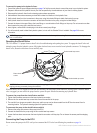
7. Add hydraulic hose from the return connector at the back of the helm to the pump.
8. Connect the hose to the helm and to the return-line connector on the pump using the included ttings.
9. You will eventually need to bleed the hydraulic system, but not until the Shadow Drive is installed. See page 24 for more
information.
NOTE: The pump may vibrate the hydraulic lines and cause noise when the autopilot is running. To eliminate the noise, tie the hydraulic
lines to a solid surface.
Connecting the Pump to the ECU
Do not connect the pump to the ECU until you have mounted the ECU to the boat following the procedures on page 16.