


13GHP 10 Marine Autopilot System Installation Instructions
Installation Procedures
After you have completely planned the GHP 10 installation on your boat, and have satised all the hydraulic, mounting, and wiring
considerations for your particular installation, you can begin mounting and connecting the components.
Installing the Pump (and Motor)
Install the pump by mounting it on your boat, connecting it to the hydraulic steering lines of your boat, and connecting it to the ECU.
If your boat uses an unbalanced-cylinder steering system, be sure you have a 2.0 L or 1.2 L pump with the unbalanced kit installed. If
your 2.0 L or 1.2 L pump does not have an unbalanced kit installed, follow the directions on page 30 to install an unbalanced kit for
use with an unbalanced-cylinder steering system. Do not use a 2.1 L pump with an unbalanced-cylinder steering system.
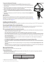
Mounting the Pump
Mount the pump horizontally on a solid surface. Mounting the pump horizontally on the oor is preferable, but you can also mount the
pump horizontally on a wall. If horizontal mounting is not possible, do not install the pump vertically with the pump head (containing
the hose ttings) down. Mount the pump within 19 in. (.5 m) of the ECU. Mount the pump in a location to which you can extend
the hydraulic steering lines of the boat.
To mount the pump:
1. Determine the best location for the pump on your boat, satisfying the hydraulic and wiring considerations.
2. Determine the correct type of screws for the mounting surface. Mounting screws are included with the pump, but you may need to
provide different screws if the supplied screws are not suitable for the mounting surface.
3. Use the correct mounting template for your pump. The templates are provided on page 33. Tape the template to the mounting
location and use a center punch and hammer to mark the pilot-hole locations.
4. Drill pilot holes at the four mounting locations.
5. Use screws to mount the pump.
NOTE: To reduce noise while the autopilot is running, install a vibration-isolation mounting pad between the pump and the mounting
surface.
6. Use a spray-on corrosion blocker on the pump after it is mounted and all hydraulic and electrical connections are made.
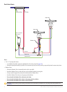
Connecting the 2.0 L or the 1.2 L Pump to the Hydraulic Lines
Before disconnecting any hydraulic lines on your boat, consult the manufacturer of your boat or steering system. You must know how
to properly prepare the hoses for removal, and you must know how to properly bleed the hydraulic system of air when you complete
the connections. When adding hydraulic hose to the steering system, only use hose with machine-crimped or eld-replaceable
ttings that have a minimum rating of 1000 lb/in
2
.
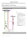
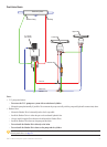
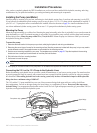
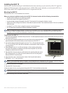
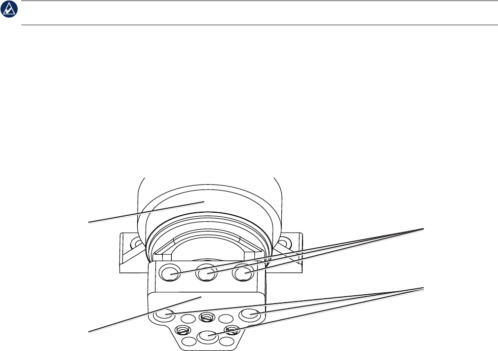
The 2.0 L and the 1.2 L pump manifolds have two sets of hose-connector ttings, both upper and lower, to allow for different
hose congurations. You can use the upper ttings, the lower ttings, or a combination of the two. Do not use Teon tape on any
hydraulic tting. Use an appropriate thread sealant such as Loctite Pro Lock Tight multipurpose anaerobic gel, part number 51604, or
equivalent, on all pipe threads in the hydraulic system.
Pump/motor body
Upper ttings
Lower ttings
Pump manifold