Installation Introduction
6
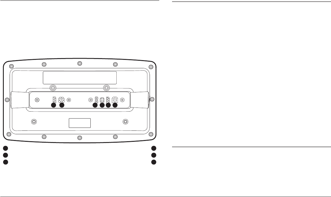
Video-Out and RS 232 Connectors
Your unit has a built-in Video Out connector and a dual RS 232 connector,
which can be used with optional-purchase equipment such as AIS
(Automatic Identification System). If you purchase a video monitor and
attach it to your control head using the Video Out connector, your unit will
send a video signal if it detects a monitor. See Setup Menu Tab: Video Out
for more information.
NOTE: Accessories connected to the RS 232 or Video-Out connectors require a
separate power source.
Installation Overview
Inside the boat there is often a channel or conduit used for other wiring, this
can be used to route cables. Be sure to route the cable as far as practical
from the antenna cable of VHF radios or tachometer cables to reduce the
possibility of interference. The transducer and GPS receiver cables should
not be cut, and care should be used not to damage the cable insulation.
Basic installation tasks that you must perform include:
• Installing the control head (choose gimbal or in-dash mounting,
where in-dash mounting requires a separate purchase)
• Installing the transducer (choose the installation method that
matches your transducer)
• Installing the GPS Receiver (if included)
• Testing the complete installation and locking the transducer position
NOTE: Accessories may require a separate purchase. You can visit our web site
at humminbird.com to order these accessories online or contact our Customer
Resource Center at 1-800-633-1468.
Control Head Installation
You have two choices for mounting your control head, Gimbal mounting,
where you use a surface on the boat, such as the dash, to mount the control
head so that it can be tilted up or down, or In-dash mounting, which requires
a separate purchase.
RS 232
1
Video Output
2
Power
3
32 4
Temp/Speed
Communications/GPS
Transducer
4
5
6
1 5 6


