


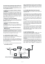
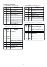

Input port for the strobe signal.
Input port for the clock signal.
Outputs the serial data to the CPU
(LOGIC unit; IC33).
Input port for the received AF signal.
Outputs the adjusted AF signal for the
repeater output.
Outputs the adjustment signal for the
PLL reference frequency on the RX
unit.
Outputs the BPF tuning signal to the
RX unit.
6
7
8
9
10
14
15
DA2STB
SCK
SDTO
AFFTTI
AFATTO
RVCON
TUNE
Pin Port
Description
number name
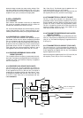
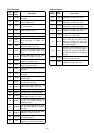
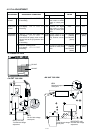
3-6-4 D/A CONVERTER IC (LOGIC UNIT; IC25)
3 - 6
Outputs the switch control signal for
the received AF signal to the micro-
phone amplifier.
Outputs the control signal for nar-
row/wide bands.
Outputs the control signal for the +9V
regulator on the RX unit.
Outputs the control signal for the M9V
regulator on the Rx unit and TX unit.
Output the detection signals whether
optional boards are installed or not.
Outputs the speaker mute signal for
the received AF.
Outputs the speaker mute signal for
the received 2/5TONE and DTMF
signals.
Outputs the MIC mute signal for the
hand microphone.
Outputs the MIC mute signal for the
REMOTE connector.
Outputs the pulse control signal for
the telephone dialer IC
Outputs the MOD mute signal for
AF signal from the telephone line.
Outputs the telephone mute signal for
the received AF signal.
Outputs the MIC mute signal for the
ACC connector.
AFMUTE1
AFMUTE2
MICMUTE1
MICMUTE2
TELBMR
TELMUTE2
TELMUTE1
MICMUTE3
4
5
6
7
11
12
13
14
Pin Port
Description
number name
R/BSW
W/NS
R9C
M9C
OPT1
OPT3
5
6
7
12
13
14
Pin Port
Description
number name
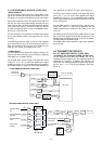
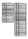
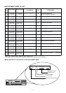
3-6-2 EXPANDER IC (LOGIC UNIT; IC40)
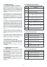
3-6-3 EXPANDER IC (LOGIC UNIT; IC41)
BASL
RMTL
BUSYL
TXL
D5C
PROGL
DCL
Outputs the control signal for “BASE”
LED on the FRONT unit.
Outputs the control signal for
“REMOTE” LED on the FRONT unit.
Outputs the control signal for “BUSY”
LED on the FRONT unit.
Outputs the control signal for “TX”
LED on the FRONT unit.
Outputs the control signal for the D5V
on the FRONT unit.
Outputs the control signal for “P” LED
on the FRONT unit.
Outputs the control signal for “DC”
LED on the FRONT unit.
4
5
6
7
12
13
14
Pin Port
Description
number name
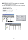
3-6 PORT ALLOCATIONS
3-6-1 EXPANDER IC (LOGIC UNIT; IC39)