


SECTION 3 CIRCUIT DESCRIPTION
3 - 1
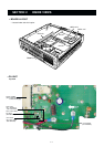
3-1 RECEIVER CIRCUITS
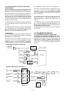
3-1-1 RF CIRCUIT
(RX
UNIT
)
Received signals from the RX antenna connector enter the
RX unit J1 and pass through a tuned bandpass filter (D3,
D4, L2, L3, C5–C8, C12, C13, C205, C206, C220, 221)
which is controlled by the D/A converter IC (LOGIC unit;
IC25). The filtered signals are applied to an RF amplifier
(Q1). The amplified signals are applied to a bandpass filter
(L6, L7, L12, L13, C9–C11, C14, C15, C21, C22, C24, C30,
C207, C208), and are then applied to the 1st mixer circuit.
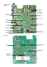
3-1-2 1ST MIXER AND 1ST IF CIRCUITS (RX UNIT)
The 1st mixer circuit converts the received signals to a fixed
frequency of the 1st IF signal with the PLL output frequency.
By changing the PLL frequency, only the desired frequency
will pass through a crystal filter at the next stage of the 1st
mixer.
The filtered signals are applied to the 1st mixer circuit (L8,
L9, L10, IC1) and are then mixed with the 1st LO signal from
the PLL circuit to produce a 31.65 MHz 1st IF signal.
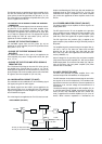
The 1st IF signal passes through a MCF (Monolithic Crystal
Filter; FI1) to suppress out-of-band signals. The filtered sig-
nal is applied to the 2nd mixer circuit (IC2, pin 16) via the
buffer amplifier (Q3).
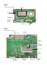
3-1-3 2ND IF AND DEMODULATOR CIRCUITS
(RX UNIT)
The 2nd mixer circuit converts the 1st IF signal to a 2nd IF
signal. A double-conversion superheterodyne system
improves the image rejection ratio and obtains stable receiv-
er gain.
The amplified signal is applied to the 2nd mixer section of
the FM IF IC (IC2, pin 16), and is then mixed with the 2nd
LO signal for conversion to a 455 kHz 2nd IF signal.
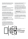
IC2 contains the 2nd mixer, limiter amplifier, quadrature
detector, active filter and noise amplifier circuits, etc. The
local oscillator section and X2 generate 31.195 MHz for the
2nd LO signal.
The 455 kHz 2nd IF signal is applied to a ceramic bandpass
filter (narrow; FI5, wide; FI6) where unwanted signals are
suppressed and are then applied to a limiter amplifier sec-
tion in the system IC (IC2, pin 5).
The 2nd LO signal is then amplified at the limiter amplifier
section (IC2, pin 5) and applied to the quadrature detector
section (IC2, pins 10, 11 and X1) to demodulate the 2nd IF
signal into AF signals.
The AF signals are output from pin 9 (IC2) and are then
applied to the AF amplifier circuit on the LOGIC unit.
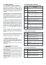
3-1-5 AF AMPLIFIER CIRCUIT (LOGIC UNIT)
The AF amplifier circuit amplifies the demodulated AF sig-
nals to drive a speaker.
The AF signals from the FM IF IC (RX unit; IC2, pin 9) are
applied to a buffer amplifier (IC9, pins 8, 9). The amplified
signals pass through the high-pass filter (IC9, pins 5, 7, 12,
14) which removes CTCSS or DTCS signals.
The filtered AF signals are output from pin 7 (IC9), and are
applied to the de-emphasis circuit (IC9, pins 1, 2) with fre-
quency characteristics of –6 dB/octave, and then passed
through a low-pass filter (IC10, pins 1, 3, 5, 7). The filtered
signal is applied to a volume control (VR unit; R1) to control
the audio level.
IC2 contains the 2nd mixer, limiter amplifier, quadrature
detector, active filter and noise amplifier circuits, etc. The
local oscillator section and X2 generate 31.195 MHz for the
2nd LO signal.
The output AF signals from a volume control (VR unit; R1)
pass through the analog switch IC (IC16, pins 1, 7), and are
then applied to the AF power amplifier (IC17, pins 1, 4) to
drive a speaker.
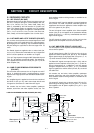
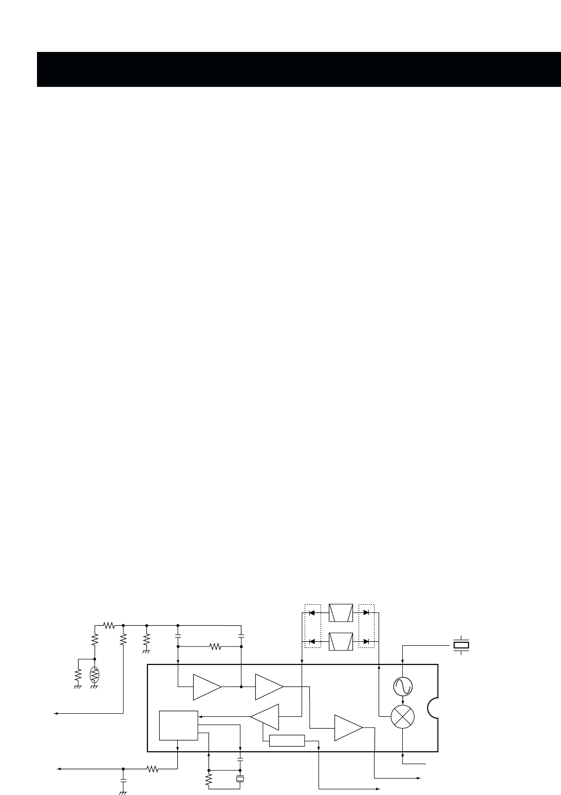
• 2ND IF AND DEMODULATOR CIRCUITS (RX UNIT)
FI5
2nd IF filter
455 kHz
IF
amp.
QUAD.
detector
Active
filter
"DISC" signal to
LOGIC unit J1
X1
RSSI
2nd
Mixer
X2
1st IF from the IF amplifier (Q3)
"RSSI" signal to the CPU
8
7
531
16
13
11
109
IC2
TA31136FN
Noise
comp.
Noise
amp.
12
FI6
"N-DET" to the CPU
"SQL" signal to the
LOGIC unit J1
NARROW
WIDE