


4 - 6
*The output level of the standard signal generator (SSG) is indicated as the SSG’s open circuit.
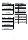
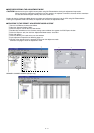
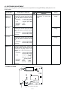
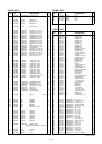
4-3 SOFTWARE ADJUSTMENT
Select an item using [CH-UP] / [CH-DN] buttons, then set specified value using [RPT/BASE] / [MONI] buttons on the
FRONT PANEL.
Maximum
voltage
Maximum
voltage
Maximum
voltage
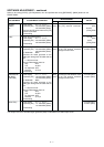
Squelch open
1
2
3
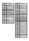
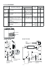
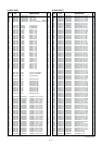
• LCD display :
A02 LW HRTUN
• Connect the standard signal generator
to the [RX] antenna connector and set
as:
Frequency : 171.9250 MHz
[GEN74]
173.9250 MHz [Other]
Level : 32 µV* (–77 dBm)
Modulation : 1 kHz
Deviation : ±3 kHz
• Receiving
• LCD display :
A03 LW MRTUN
• Connect the standard signal generator
to the [RX] antenna connector and set
as:
Frequency : 160.0750 MHz
[GEN74]
162.0750 MHz [Other]
• Receiving
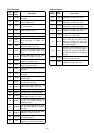
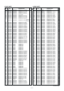
• LCD display :
A04 LW LRTUN
• Connect the standard signal generator
to the [RX] antenna connector and set
as:
Frequency : 148.0750 MHz
[GEN74]
150.0750 MHz [Other]
• Receiving
• LCD display :
A05 LW RPTSQL
• Connect a standard signal generator to
the [RX] antenna connector and set as:
• Connect the RF power meter or 50 Ω
dummy load to the [TX] antenna con-
nector.
Frequency : 148.0750 MHz
[GEN74]
150.0750 MHz [Other]
Level : 0.2 µV* (–121 dBm)
[Other]
: 0.32 µV* (–117 dBm)
[EUR2], [FRG2]
Modulation : 1 kHz
Deviation : ±3 kHz [Other]
: ±2.4 kHz [FRG2]
• Receiving
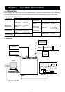
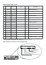
RX
SENSITIVITY
(HIGH FRQ.)
(MID FRQ.)
(LOW FRQ.)
REPEATER
SENSITIVITY
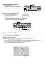
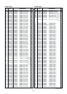
RX
FRONT
Connect the digital multi meter or
oscilloscope to check point
CP18.
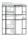
Speaker
ADJUSTMENT ADJUSTMENT CONDITION
MEASUREMENT
VALUE
UNIT
LOCATION
CP18
CP1
CP18
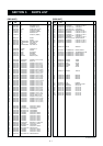
RX sensitivity chack point
• RX UNIT TOP VIEW