


4 - 8
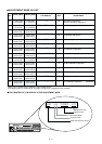
*The output level of the standard signal generator (SSG) is indicated as the SSG’s open circuit.
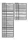
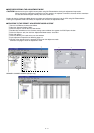
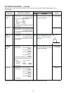
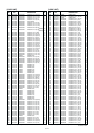
SOFTWARE ADJUSTMENT – continued
Select an item using [CH-UP] / [CH-DN] buttons, then set specified value using [RPT/BASE] / [MONI] buttons on the
FRONT PANEL.
±0.65 kHz
[Other]
±0.52 kHz
[FRG2]
±0.35 kHz
±3.0 kHz
[Other]
±2.4 kHz
[FRG2]
±1.5 kHz
1
2
1
2
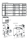
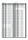
• LCD display :
A10 LW CDCDEV
• Operating freq. : 160.2750 MHz
[GEN74]
162.2750 MHz [Other]
• Set the FM deviation meter as:
HPF : OFF
LPF : 20 kHz
De-emphasis: OFF
Detector : (P–P)/2
• No audio applied to the [MIC] connector.
• Transmitting
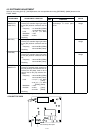
• LCD display :
A12 LN CTCDEV
• Operating freq : 160.2750 MHz
[GEN74]
162.2750 MHz [Other]
• No audio applied to the [MIC] connector.
• Transmitting
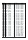
• LCD display :
A11 LW DTCADJ
• Operating freq. : 160.2750 MHz
[GEN74]
162.2750 MHz [Other]
• No audio applied to the [MIC] connector.
• Transmitting.
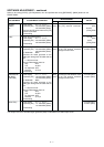
• LCD display :
A13 LW RPTAF
• Operating freq : 158.2750 MHz (RX)
[GEN74]
160.2750 MHz (TX)
[GEN74]
160.2750 MHz (RX)
[Other]
162.2750 MHz (TX)
[Other]
• Connect the standard signal generator
to the RX antenna connector and set
as:
Level : 1 mV* (–47 dBm)
Modulation : 1 kHz
Deviation : ±3 kHz [Other]
: ±2.4 kHz [FRG2]
• Transmitting
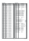
• LCD display :
A14 LN RPTAF
• Operating freq : 158.2750 MHz (RX)
[GEN74]
160.2750 MHz (TX)
[GEN74]
160.2750 MHz (RX)
[Other]
162.2750 MHz (TX)
[Other]
• Transmitting
CTCSS
DEVIATION
(WIDE)
(NARROW)
DTCS
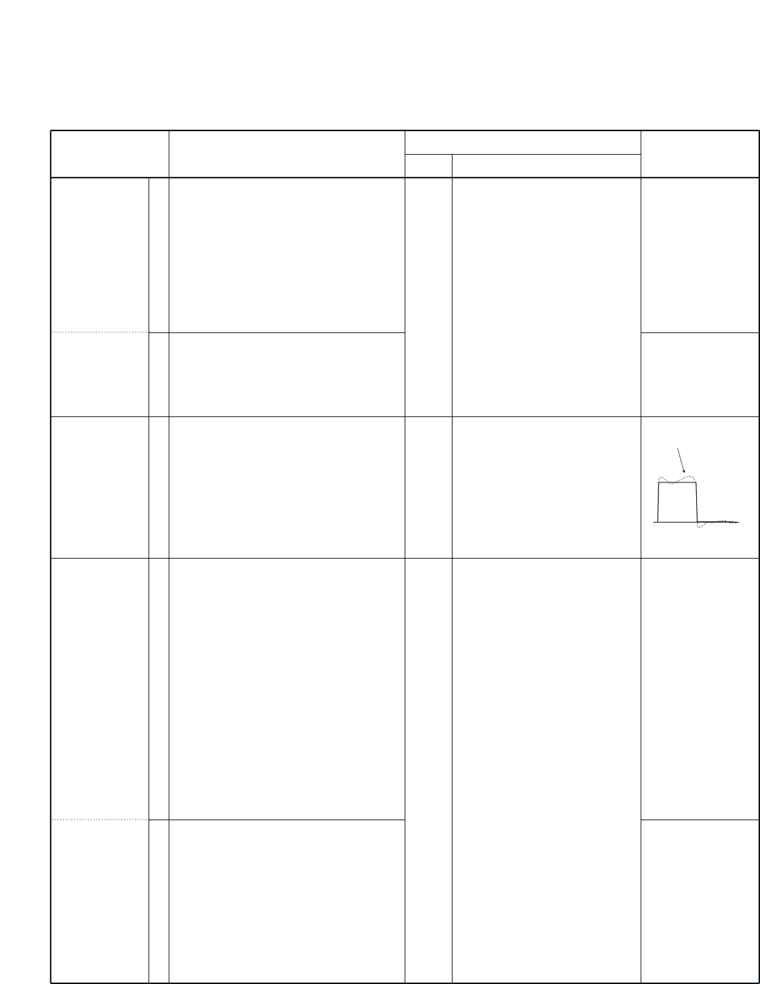
MODULATION
BALANCE
REPEATER
DEVIATION
(WIDE)
(NARROW)
Rear
panel
Rear
panel
Rear
panel
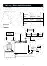
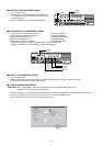
Connect the FM deviation meter
to the [TX] antenna connector
through the attenuator.
Connect the FM deviation meter
with an oscilloscope to the [TX]
antenna connector through the
attenuator.
Connect the FM deviation meter
to the [TX] antenna connector
through the attenuator.
ADJUSTMENT ADJUSTMENT CONDITION
MEASUREMENT
VALUE
UNIT LOCATION
Set to flat wave
form