


6 - 2
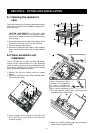
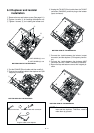
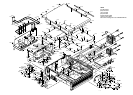
6-3 Duplexer and isolater
installation
q Remove the top and bottom covers (See page 6-1).
w Tighten 4 screws, A, for installing the duplexer unit.
3 Tighten 4 screws, B, for installing the isolater unit.
4 Cut the RX ANT-RX unit cable and then modify it.
5 Connect the modified cable to the duplexer unit (RX
frequency connector)
6 Unplug the TX ANT–PA unit cable from the TX ANT
connecter (CHASSIS), and then plug to the isolater
(input connector).
7 Connect the *cable between the isolator (output
connector) and the duplexer (TX frequency connec-
tor).
8 Connect the *cable between the duplexer (ANT
connector) and the TX ANT connector (CHASSIS).
9 Return the top and bottom cover to their original po-
sition.
A
A: SET SCREW (C) 3×10
B: SET SCREW (H) 3×8
B
B
BOTTOM VIEW OF THE REPEATER
6
BOTTOM VIEW OF THE REPEATER
4
5
BOTTOM VIEW OF THE REPEATER
BOTTOM VIEW OF THE REPEATER
8
7
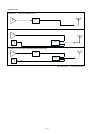
RX ANT-RX unit cable modification
Cut the wire here.
Plug the cable to the duplexer.
Solder the cable with connector.
CUT
DUPLEXER
*NOTE: Connection cable are not supply with the iso-
later and the duplexer. Therefore, need to
make them by yourself.