


3 - 2
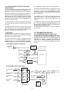
3-1-6 RECEIVER MUTE CIRCUITS (LOGIC UNIT)
• NOISE SQUELCH
The noise squelch circuit cuts out AF signals when no RF
signals are received. By detecting noise components in the
AF signals, the squelch circuit switches the AF mute switch.
Some noise components in the AF signals from the FM IF IC
(RX unit; IC2, pin 9) are passed through the SQL level con-
troller (VR unit; R2). The level controlled signals are applied
to the active filter section in the FM IF IC (RX unit; IC2, pin
8). Noise components about 10 kHz are amplified and out-
put from pin 7 (RX unit; IC2).
The filtered signals are converted to the pulse-type signals
at the noise detector section and output from pin 13 (RX
unit; IC2).
The NDET signal from the FM IF IC (RX unit; IC2) is applied
to the CPU (IC33, pin 40). The CPU analyses the noise con-
dition and controls the AF mute signal via “AFMUTE1” line
(IC40, pin 4) to the AF mute switch (IC16, pin 5).
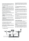
• TONE SIGNALS
The tone squelch circuit detects AF signals and opens the
squelch only when receiving a signal containing a matching
subaudible tone (CTCSS or DTCS).
The CTCSS signal passes through a low-pass filter circuit
(IC8, pins 1, 3, 5, 7, 8, 10), and is then applied to the signal
amplifier (IC8, pins 13, 14). The amplified signal is applied to
the CTCSS decoder IC (IC29, pin 16) and the detected sig-
nal is applied to the CPU (IC 33) via the serial signal line.
The DTCS signal passes through a low-pass filter circuit
(IC12, pins 1, 3, 8, 10), and is then applied to the signal
amplifier (IC12, pins 12, 14). the amplified signal is applied
to the DTCS decoder which is inside the CPU (IC33, pin 52)
via the “DTCSI” line.
The 2/5TONE signals are passes through a low-pass filter
circuit (IC12, pins 5, 7), and are then applied to the 2/5
TONE decoder which is inside the CPU (IC33, pin 51) via
“25TI” line.
The DTMF signal is pass through the DTMF switch IC (IC30
pin 7), and is then applied to the DTMF decoder(IC31). The
decoded signal is applied to the CPU (IC33, pins 82, 85, 86).
The CPU analyzes the DTMF signal.
The DTMF switch (IC30) selects the signal from telephone
line or RX unit.
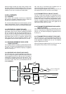
3-2 TRANSMITTER CIRCUITS
3-2-1 AF AMPLIFIER CIRCUIT (LOGIC UNIT)
• IN CASE OF THE AF SIGNALS FROM THE MIC JACK
The AF signals from the MIC jack (FRONT unit; J7) are
amplified at the AF amplifier (IC1). The amplified signals are
mixed with the “E_MOD1”, “E_MOD2” and “TELAFO” sig-
nals at IC2. The mixed signals pass though the high-pass fil-
ter (IC2, pins 1, 2, 6, 7) via the pre-emphasis circuit (IC2,
pins 8, 9).
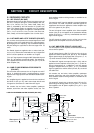
• TONE SIGNALS CIRCUITS (LOGIC UNIT)
DTMF
SW
LPF
LPF
LPF
AMP
AMP
CTCSS
DTCS
2/5TONE
DTMF
CTCSS
DETECTOR
DTMF
DECODER
CPU; IC33
DATA BUS
DATA BUS
DISC signal
from RX unit
To the AF amplifier
AMP
IC9
IC8
IC12
IC31
IC30
IC12
IC12
IC8
IC29
DTCSI
25TI
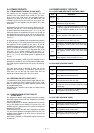
• AF AMPLIFIER CIRCUITS (LOGIC UNIT)
AMP
AMP
AMP
AMP
SW-D
SW-C
SW-B
SW-A
AMP
MIX
PRE
EMP
HPF
LIMIT
SIG
MIX
SPLAT
FIL
RPT AF
MUTE
LPF
E_MOD3
To TX unit
From the FRONT
unit
RPT AF signal
from IC25
From the telephone
circuit
From the REMOTE
connector
From the ACC
connector
From the REMOTE
connector
25TONE
BEEP
CW
DTMF
From CPU (IC33)
MIC
E_MOD
TELAFO
E_MODE2
IC13
MIC MUTE
AFATTO
IC2
IC3
IC3
IC4
IC26
IC14