


When in following seas or when running an inlet, the plates
should be fully retracted. This will allow for optimal performance.
ELECTRO-MECHANICAL ACTUATORS PROVIDE AN INSTANT
RESPONSE. WHEN MAKING ADJUSTMENTS, USE SHORT MO-
MENTARY TAPS OF THE SWITCH.
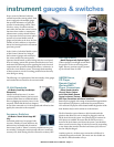
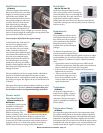
Ballast Empty/Fill Switches
(On Ballast-equipped Models Only)
On boat models equipped with a ballast
system, a separate three-position switch
will allow for the lling or emptying of the
ballast tanks and/or bags. Be aware that
the engine must operate at 1500 RPM
during the ll and empty processes.
Check engine specications for related
engine idle speed, which may be too low
for the empty/ll operation to be properly
accomplished; it is likely that the boat will
need to be in motion during the lling and
emptying of the ballast system. Failure to increase engine RPM
to the required level may result in malfunction or permanent
damage to the ballast pumps that force the water through the
system. Such damage is not covered under your warranty. e
ballast controls vary in location by model, and the operator
should determine exact location prior to use. e three-position
switches are clearly marked; FILL, OFF (in center), and EMPTY.
Manual and Automatic Bilge
Pump Switch (Manual and
Automatic)
(All Models)
e bilge pumps on all V-drive models will
be in the automatic mode when the igni-
tion key is turned ON. Some models may
have two (2) switches, one for the forward bilge and one for the
a. In these instances, the switches will be marked. e manual
and automatic bilge discharge system is never completely o.
When in the automatic (default) position, a sensor alerts the
system to discharge water from the bilge area. Boat operators
are advised to leave the switch in the automatic position, unless
there appears to be excess water in the bilge. In that event, the
bilge pump can be manually activated by turning the bilge pump
switch to the manual ON position. Return the switch to the au-
tomatic position when nished emptying the bilge. Leaving the
switch in manual mode can result in damage to the pump and
may not be covered by warranty!
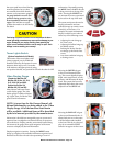
Blower Switch
(All Models)
A two-position rocker switch activates the
engine box ventilation blower. Push the top
half of the switch to turn the blower ON.
Note: e blower must operate for a mini-
mum of four (4) minutes before starting the engine at any time.
e blower must also be operated during idle and slow-speed
running, but is not necessary during cruising speed.
To prevent a possible explosion, operate the blower for at least
four (4) minutes before starting the engine and always when at
idle or slow-running speed. Explosive gasoline and/or battery
fumes may be present in the engine compartment. Failure to oper-
ate the blower as instructed may cause improper ventilation of
the boat engine and bilge areas, and fuel vapors can accumulate
in this area, causing a re or explosion which may result in death
or serious injury!
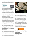
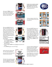
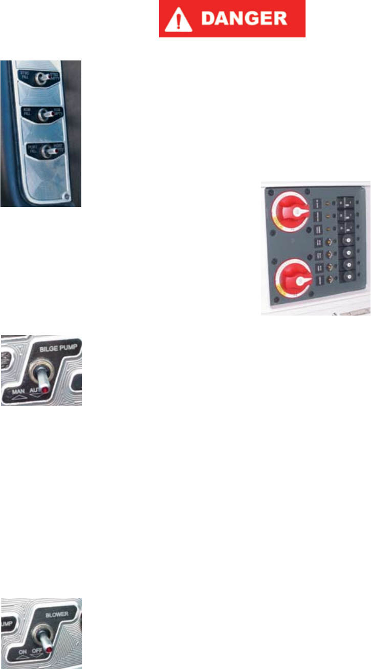
Circuit Breakers
(All Models)
All major boat circuits are pro-
tected from shorting and overload
by re-settable circuit breakers. If a
problem develops with one of the
following circuits, switch OFF the
circuit and wait for approximately
one (1) minute. en fully push
the appropriate breaker button and
switch ON the circuit. If the circuit
continues to trip, there is a problem
somewhere that must be attended to immediately. See your au-
thorized MasterCra service department to resolve this matter.
e location of the main circuit breaker board is under the dash
panel. In some models, there is an additional breaker panel to
assist with the accessory load, and where equipped is located
near the battery box. ere may also be a waterproof fuse for
the stereo amplier, where equipped. If the boat’s accessories are
malfunctioning, check and then re-set breakers as necessary.
e engines are also equipped with breaker systems. e main
35A circuit breaker protects the engine electrical system and
components from overload. If the engine will not turn over with
the battery switch in the ON position, locate the red breaker re-
set button (labeled “35”) in the engine. ere will be an audible
click. Try again to start the engine. If the breaker trips again, the
engine requires attention. Immediately take your boat to your
authorized MasterCra service department.
In addition to the 35A circuit breaker, the engines are equipped
with additional component overload protection, including a 15A
ATO fuse for the fuel pump, a 15A ATO fuse for the injectors
and a 15A ATO fuse for the ECM unit.
If you suspect that any of these fuses may not be operating as
designed, you should take your boat to your authorized Master-
Cra service department for inspection and repair.
If during maintenance or inspection it becomes necessary
to remove or re-position any of the engine’s wiring or wire
MasterCraft 2009 Owner’s Manual - Page 5-3