


harness(es) verify that the wiring has been returned to its origi-
nal position and that all harnesses are routed correctly before
attempting to use the boat again. If a wiring clip or retainer
breaks, replace it immediately. Wiring is specically routed to
eliminate problems related to engine heat and spray or immer-
sion in liquids. Electrical problems may result if wiring is moved
from its original position!
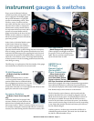
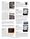
Clock Adjustment Switch
(MariStar Models)
MariStar models are equipped with a clock adjustment switch, which
is a three-position switch that is pressed upward or downward to add
or subtract time to the clock. e middle position is OFF.
Courtesy Lights Switch
(All Models)
is switch is a two-position switch that ac-
tivates the courtesy lights within the boat.
Turning the switch upwards will turn the
lights ON, and turning it downwards will
turn the lights OFF.
Cruise Control Gauge
(Where Equipped)
Boats equipped with cruise control systems pro-
vide short manuals that describe how to operate
and maintain the cruise control system. Refer to
the appropriate manual prior to operation of the
system. Boats featuring the “simple” cruise system
function the same as an automobile with an ON/
OFF switch and +/- to increase or decrease speed.
Display Selector Switch
(ProStar 190, ProStar 197, X-7)
On the models equipped with the Multi-Function
gauge, this switch allows the operator to toggle be-
tween functions.
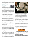
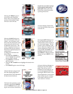
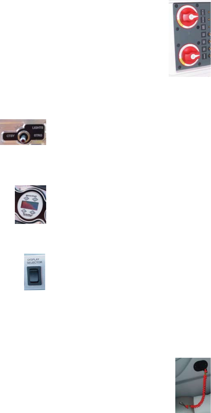
Dual Battery Operation Switch
(All MariStar Models and Similar X Series, X-Star,
CSX 220, CSX 265)
MariStar and X-Star: For normal operation the battery switch
should be placed in the ON position. is allows the engine and
all accessories to receive power. e engine will recharge both
batteries with the switch ON. For transportation and storage,
the battery switch should be placed in the OFF position to allow
both batteries to be isolated from all circuits.
Note: e switch knob may be removed when it is in the OFF posi-
tion. is is a security feature.
If the engine will not start because the battery is discharged, the
engine may be started from the house battery by placing the switch
in the COMBINE BATTERIES position. Aer
the engine is started, the switch should be re-
turned to the ON position and NOT allowed to
remain in the COMBINE Batteries mode.
MariStar 280 and X-80: For normal operation
the port and starboard battery switches should
be placed in the ON position. e COMBINE
BATTERIES switch should remain OFF. e
engine and all accessories will receive power.
Note: e port battery is a dedicated start
battery for the port engine and the starboard battery provides
starting current of the starboard engine while also providing
power for accessory circuits. For transportation and storage, all
battery switches should be placed in the OFF position to isolate
both batteries from all circuits.
NOTE: e switch knob may be removed when it is in the OFF
position. is is a security feature.
If either battery becomes discharged, start the engine with
the remaining charged battery and THEN set the COMBINE
BATTERIES switch to ON. e remaining engine may then be
started. Return the COMBINE BATTERIES switch to OFF. e
COMBINE BATTERIES switch should NOT be le ON.
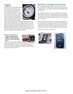
CSX 220 and 265: e CSX 220 and CSX 265 are equipped with
dual batteries. One battery is reserved to provide engine starting
power and the other provides power for all electrical accessories.
ese batteries are located under the starboard rear seat cushion.
To facilitate access, the batteries are mounted on a sliding tray,
which is secured with a pin. Remove the pin to slide the tray
forward for battery maintenance.
Outside this compartment, located on the side of the deck under
the starboard seat is the battery switch box. For normal opera-
tion of the boat, the switch should be set to ON. For transpor-
tation and storage, the switch should be moved to OFF. In the
event of a failure of the starter battery, the two batteries may be
combined to provide additional power to start the engine. is
can be done by setting the battery switch to COMBINE BAT-
TERIES and starting the engine as normal. Aer the engine is
started, the switch should be returned to the ON position.
e battery charger inlet connector is also located in the battery
switch box. Please see information provided by the charger
manufacturer. Battery chargers installed by MasterCra are of
the charger/maintainer variety. e charger may be le con-
nected to the batteries indenitely.
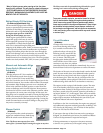
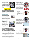
Engine Emergency
Safety Stop Switch
(All Models)
e engine emergency safety stop switch, called
the lanyard, is an ignition cut-o switch designed
to stop the engine in the event the operator is
thrown or moves too far away from the helm.
MasterCraft 2009 Owner’s Manual - Page 5-4