


5
INSTALLATION
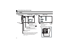
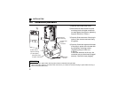
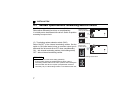
2.2 Installation procedure
1) Remove the inverter front cover.
2) Mount the hex-head screw for option
mounting into the inverter screw hole
(on earth plate) (size 5.5mm, tightening
torque 0.56Nxm to 0.75Nxm).
3) Securely fit the connector of the plug-in
option to the inverter connector along
the guides.
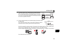
4) Securely fix the both right and left sides
of the plug-in option to the inverter with
the accessory mounting screws.
(Tightening torque 0.33Nxm to
0.40Nxm)
If the screw holes do not line up, the
connector may not have been plugged
securely. Check for loose plugging.
REMARKS
• Remove a plug-in option after removing two screws on both left and right sides.
(When the plug-in option is mounted in the connector 3), it is easier to remove the plug-in option after removing a
control circuit terminal block.)
4) Mounting
screws
Inverter side
option
connector
Screw hole for
option mounting
Screw hole for
option mounting
(on earth plate)
Hex-head screw
for option mounting
1)
2)
3)