


6
INSTALLATION
2
CAUTION
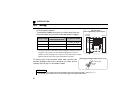
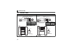
• Only one type of option per inverter may be used. When two or more options are mounted, priority is in the
order of inverter option connectors 1, 2 and 3. The options having lower priority are inoperative.
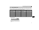
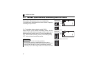
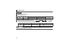
• When the inverter cannot recognize that the option is mounted due to improper
installation, etc., " to " (option fault) are displayed. The errors
shown differ according to the mounting positions (connectors 1, 2, 3).
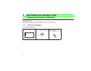
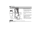
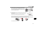
• When mounting/removing an option, hold the sides of the option. Do not press
on the parts on the option circuit board. Stress applied to the parts by pressing, etc. may cause a failure.
• Take caution not to drop a hex-head screw for option mounting or mounting screw during mounting and
removal.
• Pull the option straight out when removing. Pressure applied to the connector and to the option circuit
board may break the option.
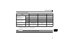
Mounting
Position
Error
Display
Connector 1
Connector 2
Connector 3