


15
INSTALLATION
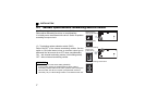
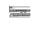
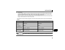
2.6 Encoder
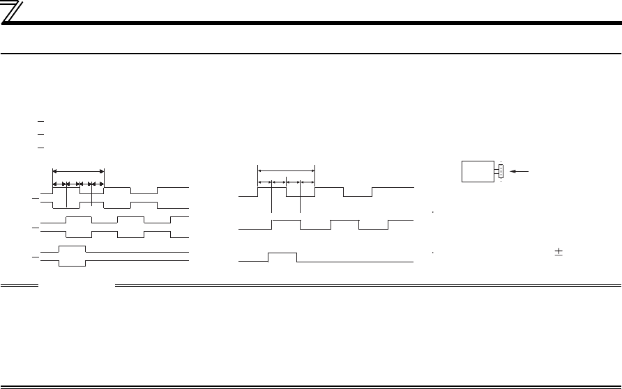
(1) Position detection (pulse encoder)
CAUTION
⋅ When orientation control, encoder feedback control, vector control are used together, the encoder is shared
between these controls.
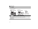
Use an encoder which has a pulse count of 1000 to 4096ppr (pulse per revolution).
⋅
The encoder should be coupled with the motor shaft or the spindle oriented with a speed ratio of 1 to 1 without any
mechanical looseness.
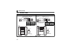
⋅ To ensure correct operation, the encoder must be set in the proper rotation direction and the A and B phases
connected correctly.
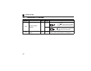
P
abcd
H
A
A
B
B
Z
Z
L
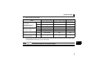
A/A signal 1000P/R to 4096P/R
B/B signal 1000P/R to 4096P/R
Z/Z signal 1P/R
A signal 1000P/R to 4096P/R
B signal 1000P/R to 4096P/R
Z signal 1P/R
Differential line driver Complementary
Output pulse specifications
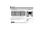
A
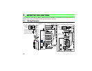
Position detector
Encoder
When rotation is clockwise
as viewed from the shaft
end (A) of the encoder.
a, b, c, d should be (1/4
1/8)P
A
B
Z
abcd
P