


34
VECTOR CONTROL
5
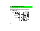
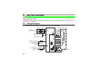
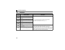
*1 The pin number differs according to the encoder used.
Speed and torque controls are available with or without the Z-phase being connected.
*2 Connect the encoder so that there is no looseness between the motor and motor shaft. Speed ratio should be 1:1.
*3 Earth (Ground) the shielded cable of the encoder cable to the enclosure with a P clip, etc. (Refer to page 9.)
*4 For the complementary, set the terminating resistor selection switch to off position. (Refer to page 7.)
*5 A separate power supply of 5V/12V/15V/24V is necessary according to the encoder power specification. When
the encoder output is the differential line driver type, only 5V can be input.
Make the voltage of the external power supply the same as the encoder output voltage, and connect the external
power supply between PG and SD.
When performing orientation control together, an encoder and power supply can be shared.
*6 For terminal compatibility of the FR-JCBL, FR-V7CBL and FR-A7AP, refer to page 14.
*7 For the fan of the 7.5kW or less dedicated motor, the power supply is single phase. (200V/50Hz, 200 to 230V/
60Hz)
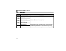
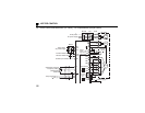
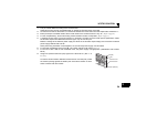
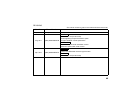
*8 Assign OH (external thermal input) signal to the terminal CS. (Set "7" in
Pr. 186 )
Connect a 2W1kΩ resistor between the terminal PC and CS (OH). Install
the resistor pushing against the bottom part of the terminal block so as to
avoid a contact with other cables.
CS(OH)
Resistor (2W1kΩ)
PC
Control circuit
terminal block