


PowerLogic
TM
E4800 Series 930-110-01
Introduction 02/2009
© 2009 Schneider Electric All Rights Reserved4
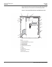
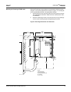
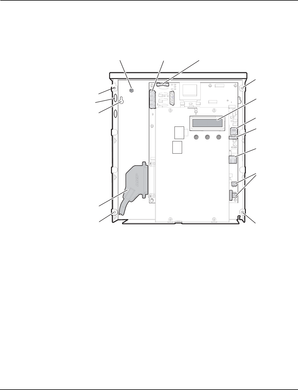
Figure 2 shows the internal view of the PowerLogic E4833 and PowerLogic
E4880. See Figure 3 for the internal view of the PowerLogic E4805.
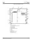
Figure 2: PowerLogic E4833 and PowerLogic E4880 internal view
1
2
3
4
5
6
7
8
9
10
11
12
1
1
1
Legend:
1 Cover screw location
2 Current transformer input connector
3 Mounting keyhole
4 Conduit knockout
5 Earth connection
6 Voltage input terminal block
7 Fuse
8 Display
9 Modem port
10 RS232 for remote display
11 Ethernet port
12 Pulse in terminal blocks