930-110-01 PowerLogic
TM
E4800 Series
02/2009 Installation
© 2009 Schneider Electric All Rights Reserved
19
8. Repeat steps 5 to 7 for remaining CTs.
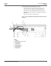
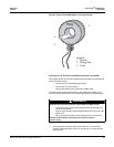
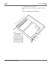
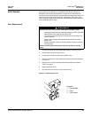
Figure 10 shows the 5A CT wiring harness connected to the PowerLogic
E4805.
Figure 10: Connecting the 5A CT wiring harness
P8
P7
P6
6
P5
P4
P3
P2
P1
1
2
3
3
1
Legend:
1 Cable tie-down point
2 10/100 BaseTX Ethernet port
3 Pulse in terminal block
P1 Meter point 1 connector plug
P2 Meter point 2 connector plug
P3 Meter point 3 connector plug
P4 Meter point 4 connector plug
P5 Meter point 5 connector plug
P6 Meter point 6 connector plug
P7 Meter point 7 connector plug
P8 Meter point 8 connector plug
+
+
_
_


