PowerLogic
TM
E4800 Series 930-110-01
Installation 02/2009
© 2009 Schneider Electric All Rights Reserved16
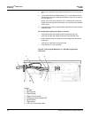
2. Feed the free end of the cable through the bottom left of the meter
enclosure.
This cable is made up of twisted-pair wires for connecting the individual
CTs to the current inputs. The color codes for the black (positive or X1)
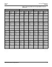
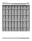
and white (neutral or X2) connections for each CT are listed in Table 2
on page 17.
NOTE: The direction of the energy flow is indicated on the CT.
3. Turn off all power to the distribution panel where the CTs are being
installed. Always use a properly rated voltage sensing device to confirm
power is off.
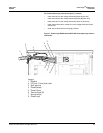
4. Feed the CT cable into the distribution panel through an appropriate
punch-out with an approved strain relief.
5. Strip the plastic sheaths back on the cable to an appropriate length to
expose the wire pairs. Cut and strip the CT leads and wire pair leads to
an appropriate length. Crimp the CT leads to the wire pairs for each
meter point.
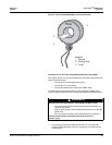
6. When using solid-core CTs, remove the feed cable from the circuit
breaker, place the CT over the wire, and reconnect feed cable to the
circuit breaker. Ensure that the arrow on the CT label is pointing in the
direction of the energy flow (toward the load).
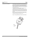
7. When using split-core CTs, separate the halves of the CT and place the
CT over the cable to the circuit breaker. Ensure that the CT is facing the
source as shown on the label. Install cable ties to ensure that the CT
halves are held together securely.
8. Repeat steps 5 to 7 for the remaining CTs.


