


© 2011 Schneider Electric. All Rights Reserved.
63230-500-225A2 PowerLogic
TM
Series 800 Power Meter
3/2011 Chapter 3—Operation
11
Chapter 3—Operation
This section explains the features of the power meter display and the power meter setup
procedures using this display. For a list of all power meter models containing an integrated
display or a remote display, see Table 1–5 on page 5.
Power Meter Display
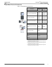
The power meter is equipped with a large, back-lit liquid crystal display (LCD). It can
display up to five lines of information plus a sixth row of menu options. Figure 3–1 shows
the different parts of the power meter display.
How the Buttons Work
The buttons are used to select menu items, display more menu items in a menu list, and
return to previous menus. A menu item appears over one of the four buttons. Pressing a
button selects the menu item and displays the menu item’s screen. When you have
reached the highest menu level, a black triangle appears beneath the selected menu item.
To return to the previous menu level, press the button below
1;. To scroll through the menu
items in a menu list, press the button below
###: (see Figure 3–1).
NOTE: Each time you read “press” in this manual, press and release the appropriate button
beneath the menu item. For example, if you are asked to “Press PHASE,” you would press
the button below the PHASE menu item.
Changing Values
When a value is selected, it flashes to indicate that it can be modified. A value is changed
by doing the following:
• Press + (plus) or - (minus) to change numbers or scroll through available options.
• If you are entering more than a single-digit number, press <-- to move to the next
higher numeric position.
• To save your changes and move to the next field, press OK.
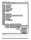
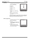
Menu Overview
Figure 3–2 on page 12, shows the first two levels of the power meter menu. Level 1
contains all of the top level menu items. Selecting a Level 1 menu item takes you to the
corresponding Level 2 menu items. Additional menu levels may be provided, depending on
the specific meter features and options.
NOTE: Press ###: to scroll through all menu items on a given level.
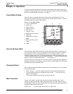
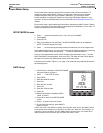
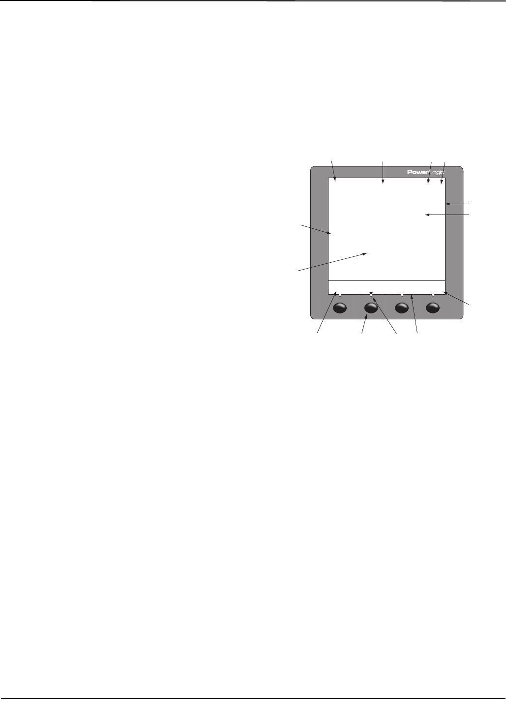
Figure 3–1: Power Meter Display
A. Type of measurement
B. Screen title
C. Alarm indicator
D. Maintenance icon
E. Bar chart (%)
F. Units (A, V, etc.)
G. Display more menu items
H. Menu item
I. Selected menu indicator
J. Button
K. Return to previous menu
L. Values
M. Phase
0(!3%
!-030%20(!3%
!
)$-$
ZZZZZ\\\\\\
!
!
!
"
#
.
)
!
ZZZZZ\\\\\\
ZZZZZ\\\\\\
ABCD
E
G
HIK
L
M
J
F
PLSD110097