


© 2011 Schneider Electric. All Rights Reserved.
PowerLogic
TM
Series 800 Power Meter 63230-500-225A2
Chapter 5—Input/Output Capabilities 3/2011
44
Step 4: Round to nearest hundredth, since the power meter only accepts 0.01 kWh
increments.
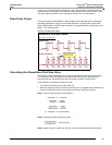
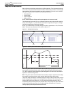
Analog Inputs
With a PM8M2222 option module installed, a power meter can accept either voltage or
current signals through the analog inputs on the option module. The power meter stores a
minimum and a maximum value for each analog input.
For technical specifications and instructions on installing and configuring the analog inputs
on the PM8M2222, refer to the instruction bulletin (63230-502-200) that ships with the
option module. To set up an analog input, you must first set it up from the display. From the
SUMMARY screen, select MAINT > SETUP > I/O, then select the appropriate analog input
option. Then, in PowerLogic software, define the following values for each analog input:
• Name—a 16-character label used to identify the analog input.
• Units—the units of the monitored analog value (for example, “psi”).
• Scale factor—multiplies the units by this value (such as tenths or hundredths).
• Report Range Lower Limit—the value the Power Meter reports when the input
reaches a minimum value. When the input current is below the lowest valid reading, the
Power Meter reports the lower limit.
• Report Range Upper Limit—the value the power meter reports when the input
reaches the maximum value. When the input current is above highest valid reading, the
Power Meter reports the upper limit.
For instructions on setting up analog inputs using software, see your software
documentation or Help file.
Analog Outputs
This section describes the analog output capabilities when a PM8M2222 is installed on the
Power Meter. For technical specifications and instructions on installing and configuring the
analog outputs on the PM8M2222, refer to the instruction bulletin (63230-502-200) that
ships with the option module.
To set up an analog output, you must first set it up from the display. From the SUMMARY
screen, select MAINT > SETUP > I/O, then select the appropriate analog output option.
Then, in PowerLogic software, define the following values for each analog input
• Name—a 16-character label used to identify the output. Default names are assigned,
but can be customized
• Output register—the Power Meter register assigned to the analog output.
• Lower Limit—the value equivalent to the minimum output current. When the register
value is below the lower limit, the Power Meter outputs the minimum output current.
• Upper Limit—the value equivalent to the maximum output current. When the register
value is above the upper limit, the Power Meter outputs the maximum output current.
For instructions on setting up an analog output using software, see your software
documentation or Help file.
0.222 kWh/second
2
------------------------------------------------- 0.1 111 kWh /pu lse=
Pulse Weight (Ke) 0.11 kWh/pulse=