


© 2011 Schneider Electric. All Rights Reserved.
PowerLogic
TM
Series 800 Power Meter 63230-500-225A2
Appendix C—Using the Command Interface 3/2011
86
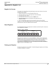
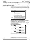
I/O Point Numbers
All inputs and outputs of the power meter have a reference number and a label that
correspond to the position of that particular input or output.
• The reference number is used to manually control the input or output with the command
interface.
• The label is the default identifier that identifies that same input or output. The label
appears on the display, in PowerLogic software
, and on the option card.
• See Table C–3 for a complete list of I/O Point Numbers
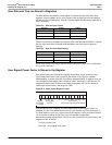
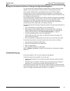
Operating Outputs from the Command Interface
To operate an output from the command interface, first identify the relay using the I/O point
number. Then, set the output to external control. For example, to energize output 1, write
the commands as follows:
1. Write number 1 to register 8001.
2. Write command code 3310 to register 8000 to set the relay to external control.
3. Write command code 3321 to register 8000.
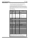
If you look in the “Relay Outputs” section of Table C–2 on page 84, you’ll see that
command code 3310 sets the relay to external control and command code 3321 is listed as
the command used to energize a relay. Command codes 3310–3381 are for use with inputs
and outputs.
Refer to “Register List Access” on page 79 for instructions on accessing the complete register list.
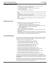
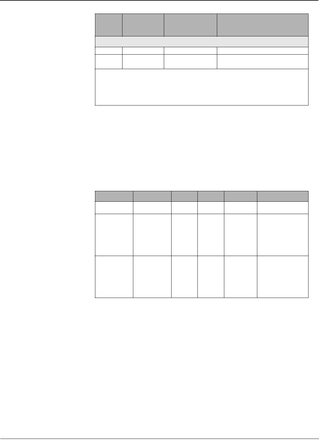
Setup
9020 None None Enter into setup mode.
9021 8001
1 = Save
2 = Do not save
Exit setup mode and save all changes.
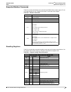
Table C–2: Command Codes
Command
Code
Command
Parameter
Register
Parameters Description
➀ You must write to register 8001 the number that identifies which output you would like to use. To determine
the identifying number, refer to“I/O Point Numbers” on page 86 for instructions.
➁ Data buffer location (register 8019) is the pointer to the first register where data will be stored. By default,
return data begins at register 8020, although you can use any of the registers from 8020–8149. Take care when
assigning pointers. Values may be corrupted if two commands are using the same register.
Refer to “Register List Access” on page 79 for instructions on accessing the complete register list.
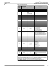
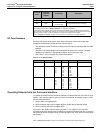
Table C–3: I/O Point Numbers
Module Standard I/O PM8M22 PM8M26 PM8M2222 I/O Point Number
—
KY
S1
———
1
2
A—
A-R1
A-R2
A-S1
A-S2
A-R1
A-R2
A-S1
A-S2
A-S3
A-S4
A-S5
A-S6
A-R1
A-R2
A-S1
A-S2
A-AI1
A-AI2
A-AO1
A-AO2
3
4
5
6
7
8
9
10
B—
B-R1
B-R2
B-S1
B-S2
B-R1
B-R2
B-S1
B-S2
B-S3
B-S4
B-S5
B-S6
B-R1
B-R2
B-S1
B-S2
B-AI1
B-AI2
B-AO1
B-AO2
11
12
13
14
15
16
17
18