


© 2011 Schneider Electric. All Rights Reserved.
PowerLogic
TM
Series 800 Power Meter 63230-500-225A2
Chapter 6—Alarms 3/2011
52
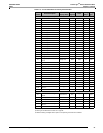
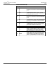
Table 6–6: Alarm Types
Type Description Operation
Standard Speed
010 Over Value Alarm
If the test register value exceeds the setpoint long enough to satisfy the pickup
delay period, the alarm condition will be true. When the value in the test register
falls below the dropout setpoint long enough to satisfy the dropout delay period,
the alarm will drop out. Pickup and dropout setpoints are positive, delays are in
seconds.
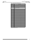
011 Over Power Alarm
If the absolute value in the test register exceeds the setpoint long enough to
satisfy the pickup delay period, the alarm condition will be true. When absolute the
value in the test register falls below the dropout setpoint long enough to satisfy the
dropout delay period, the alarm will drop out. Pickup and dropout setpoints are
positive, delays are in seconds.
012
Over Reverse
Power Alarm
If the absolute value in the test register exceeds the setpoint long enough to
satisfy the pickup delay period, the alarm condition will be true. When absolute the
value in the test register falls below the dropout setpoint long enough to satisfy the
dropout delay period, the alarm will drop out. This alarm will only hold true for
reverse power conditions. Positive power values will not cause the alarm to occur.
Pickup and dropout setpoints are positive, delays are in seconds.
020 Under Value Alarm
If the test register value is below the setpoint long enough to satisfy the pickup
delay period, the alarm condition will be true. When the value in the test register
rises above the dropout setpoint long enough to satisfy the dropout delay period,
the alarm will drop out. Pickup and dropout setpoints are positive, delays are in
seconds.
021 Under Power Alarm
If the absolute value in the test register is below the setpoint long enough to
satisfy the pickup delay period, the alarm condition will be true. When the absolute
value in the test register rises above the dropout setpoint long enough to satisfy
the dropout delay period, the alarm will drop out. Pickup and dropout setpoints are
positive, delays are in seconds.
051 Phase Reversal
The phase reversal alarm will occur whenever the phase voltage waveform
rotation differs from the default phase rotation. The ABC phase rotation is
assumed to be normal. If a CBA phase rotation is normal, the user should
reprogram the power meter’s phase rotation ABC to CBA phase rotation. The
pickup and dropout setpoints for phase reversal do not apply.
052 Phase Loss, Voltage
The phase loss voltage alarm will occur when any one or two phase voltages (but
not all) fall to the pickup value and remain at or below the pickup value long
enough to satisfy the specified pickup delay. When all of the phases remain at or
above the dropout value for the dropout delay period, or when all of the phases
drop below the specified phase loss pickup value, the alarm will drop out. Pickup
and dropout setpoints are positive, delays are in seconds.
053 Phase Loss, Current
The phase loss current alarm will occur when any one or two phase currents (but
not all) fall to the pickup value and remain at or below the pickup value long
enough to satisfy the specified pickup delay. When all of the phases remain at or
above the dropout value for the dropout delay period, or when all of the phases
drop below the specified phase loss pickup value, the alarm will drop out. Pickup
and dropout setpoints are positive, delays are in seconds.
054 Leading Power Factor
The leading power factor alarm will occur when the test register value becomes
more leading than the pickup setpoint (such as closer to 0.010) and remains more
leading long enough to satisfy the pickup delay period. When the value becomes
equal to or less leading than the dropout setpoint, that is 1.000, and remains less
leading for the dropout delay period, the alarm will drop out. Both the pickup
setpoint and the dropout setpoint must be positive values representing leading
power factor. Enter setpoints as integer values representing power factor in
thousandths. For example, to define a dropout setpoint of 0.5, enter 500. Delays
are in seconds.
055 Lagging Power Factor
The lagging power factor alarm will occur when the test register value becomes
more lagging than the pickup setpoint (such as closer to –0.010) and remains
more lagging long enough to satisfy the pickup delay period. When the value
becomes equal to or less lagging than the dropout setpoint and remains less
lagging for the dropout delay period, the alarm will drop out. Both the pickup
setpoint and the dropout setpoint must be positive values representing lagging
power factor. Enter setpoints as integer values representing power factor in
thousandths. For example, to define a dropout setpoint of –0.5, enter 500. Delays
are in seconds.
Digital
060 Digital Input On
The digital input transition alarms will occur whenever the digital input changes
from off to on. The alarm will dropout when the digital input changes back to on
from off. The pickup and dropout setpoints and delays do not apply.
061 Digital Input Off
The digital input transition alarms will occur whenever the digital input changes
from on to off.The alarm will dropout when the digital input changes back to off
from on. The pickup and dropout setpoints and delays do not apply.
070 Unary
This is a internal signal from the power meter and can be used, for example, to
alarm at the end of an interval or when the power meter is reset. Neither the
pickup and dropout delays nor the setpoints apply.