


© 2011 Schneider Electric. All Rights Reserved.
63230-500-225A2 PowerLogic
TM
Series 800 Power Meter
3/2011 Appendix C—Using the Command Interface
91
Changing Scale Factors
The power meter stores instantaneous metering data in 16-bit single registers. A value held
in each register must be an integer between –32,767 and +32,767. Because some values
for metered current, voltage, and power readings fall outside this range, the power meter
uses multipliers, or scale factors. This enables the power meter to extend the range of
metered values that it can record.
The power meter stores these multipliers as scale factors. A scale factor is the multiplier
expressed as a power of 10. For example, a multiplier of 10 is represented as a scale factor
of 1, since 10
1
=10; a multiplier of 100 is represented as a scale factor of 2, since 10
2
=100.
You can change the default value of 1 to other values such as 10, 100, or 1,000. However,
these scale factors are automatically selected when you set up the power meter, either
from the display or by using PowerLogic software.
If the power meter displays “overflow” for any reading, change the scale factor to bring the
reading back into a range that fits in the register. For example, because the register cannot
store a number as large as 138,000, a 138 kV system requires a multiplier of 10. 138,000 is
converted to 13,800 x 10. The power meter stores this value as 13,800 with a scale factor
of 1 (because 10
1
=10).
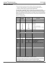
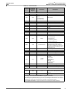
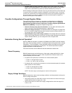
Scale factors are arranged in scale groups. You can use the command interface to change
scale factors on a group of metered values. However, be aware of these important points if
you choose to change scale factors:
• We strongly recommend that you do not change the default scale factors, which are
automatically selected by PowerLogic hardware and software.
• When using custom software to read power meter data over the communications link,
you must account for these scale factors. To correctly read any metered value with a
scale factor other than 0, multiply the register value read by the appropriate power of 10.
• As with any change to basic meter setup, when you change a scale factor, all min/max
and peak demand values should be reset.
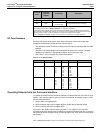
Enabling Floating-point Registers
For each register in integer format, the power meter includes a duplicate set of registers in
floating-point format. The floating point registers are disabled by default, but they can be
turned ON by doing the following:
NOTE: See “Read and Write Registers” on page 26 for instructions on how to read and
write registers.
1. Read register 11700 (Current Phase A in floating-point format). If floating-point registers
are OFF, you will see -32,768.
2. Write command code 9020 to register 8000.
3. Write 1 to register 3248.
4. Write 1 to register 8001.
5. Write command code 9021 to register 8000.
6. Read register 11700. You will see a value of 1, which indicates floating-point registers
are ON.
NOTE: Values such as current phase A are not shown in floating-point format on the
display even though floating-point registers are ON. To view floating-point values, read the
floating-point registers using the display or PowerLogic software.
Refer to “Register List Access” on page 79 for instructions on accessing the complete register list.