


© 2011 Schneider Electric. All Rights Reserved.
PowerLogic
TM
Series 800 Power Meter 63230-500-225A2
Chapter 1—Introduction 3/2011
2
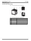
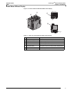
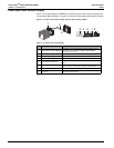
Power Meter Hardware
Power Meter With Integrated Display
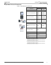
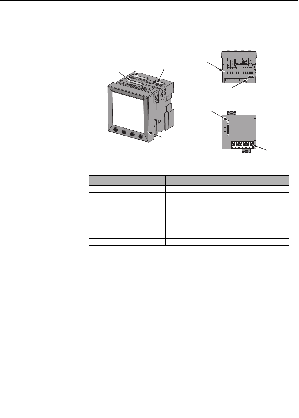
Figure 1–1: Parts of the Series 800 Power Meter with integrated display
Table 1–2: Parts of the Series 800 Power Meter with integrated display
No. Part Description
1 Control power supply connector Connection for control power to the power meter.
2 Voltage inputs Voltage metering connections.
3 I/O connector KY pulse output/digital input connections.
4 Heartbeat LED A green flashing LED indicates the power meter is ON.
5 RS-485 port (COM1)
The RS-485 port is used for communications with a monitoring and
control system. This port can be daisy-chained to multiple devices.
6 Option module connector Used to connect an option module to the power meter.
7 Current inputs Current metering connections.
8 Integrated display Visual interface to configure and operate the power meter.
1
2
3
5
6
7
4
8
Bottom View
Back View