


© 2011 Schneider Electric. All Rights Reserved.
PowerLogic
TM
Series 800 Power Meter 63230-500-225A2
Chapter 6—Alarms 3/2011
50
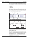
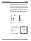
Scaling Alarm Setpoints
This section is for users who do not have PowerLogic software and need to set up alarms
from the power meter display. It explains how to scale alarm setpoints.
When the power meter is equipped with a display, most metered quantities are limited to
five characters (plus a positive or negative sign). The display will also show the engineering
units applied to that quantity.
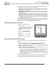
To determine the proper scaling of an alarm setpoint, view the register number for the
associated scale group. The scale factor is the number in the Dec column for that register.
For example, the register number for Scale D to Phase Volts is 3212. If the number in the
Dec column is 1, the scale factor is 10 (10
1
=10). Remember that scale factor 1 in
Table 6–3 on page 50 for Scale Group D is measured in kV. Therefore, to define an alarm
setpoint of 125 kV, enter 12.5 because 12.5 multiplied by 10 is 125. Below is a table listing
the scale groups and their register numbers.
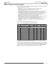
Alarm Conditions and Alarm Numbers
This section lists the power meter’s predefined alarm conditions. For each alarm condition,
the following information is provided.
• Alarm No.—a position number indicating where an alarm falls in the list.
• Alarm Description—a brief description of the alarm condition
• Abbreviated Display Name—an abbreviated name that describes the alarm condition
but is limited to 15 characters that fit in the window of the power meter’s display.
• Test Register—the register number that contains the value (where applicable) that is
used as the basis for a comparison to alarm pickup and dropout settings.
• Units—the unit that applies to the pickup and dropout settings.
• Scale Group—the scale group that applies to the test register’s metering value (A–F).
For a description of scale groups, see “Scale Factors” on page 49.
• Alarm Type—a reference to a definition that provides details on the operation and
configuration of the alarm. For a description of alarm types, refer to Table 6–6 on page
52 .
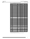
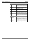
Table 6– 4 lists the default alarm configuration - factory-enabled alarms.
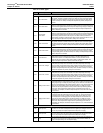
Table 6– 5 lists the default basic alarms by alarm number.
Table 6– 6 lists the alarm types.
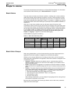
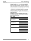
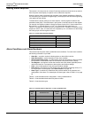
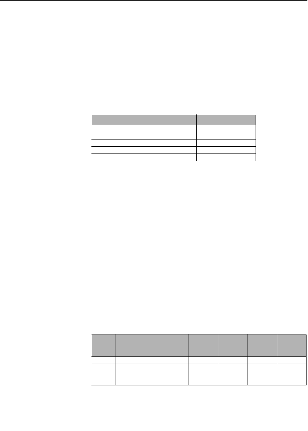
Table 6–3: Scale Group Register Numbers
Scale Group Register Number
Scale Group A—Phase Current 3209
Scale Group B—Neutral Current 3210
Scale Group C—Ground Current 3211
Scale Group D—Voltage 3212
Scale Group F—Power kW, kVAR, kVA 3214
Table 6–4: Default Alarm Configuration - Factory-enabled Alarms
Alarm
No.
Standard Alarm
Pickup
Limit
Pickup
Limit Time
Delay
Dropout
Limit
Dropout
Limit Time
Delay
19 Voltage Unbalance L-N 20 (2.0%) 300 20 (2.0%) 300
20 Max. Voltage Unbalance L-L 20 (2.0%) 300 20 (2.0%) 300
53 End of Incremental Energy Interval 0 0 0 0
55 Power-up Reset 0 0 0 0