


© 2011 Schneider Electric. All Rights Reserved.
PowerLogic
TM
Series 800 Power Meter 63230-500-225A2
Appendix C—Using the Command Interface 3/2011
84
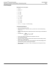
Issuing Commands
To issue commands using the command interface, follow these general steps:
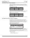
1. Write the related parameter(s) to the command parameter registers 8001–15.
2. Write the command code to command interface register 8000.
If no parameters are associated with the command, then you need only to write the
command code to register 8000. Table C–2 lists the command codes that can be written to
the command interface into register 8000. Some commands have an associated register
where you write parameters for that command. For example, when you write the parameter
9999 to register 8001 and issue command code 3351, all relays will be energized if they are
set up for external control.
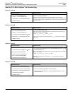
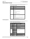
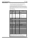
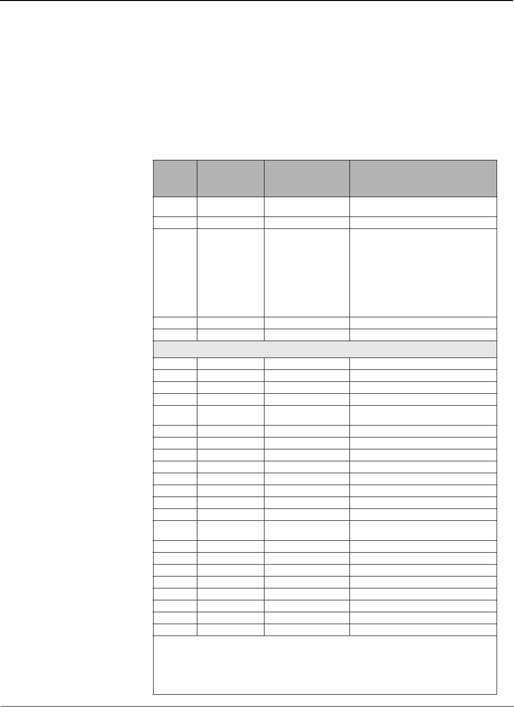
Table C–2: Command Codes
Command
Code
Command
Parameter
Register
Parameters Description
1110 None None
Causes soft reset of the unit (re-initializes the
power meter).
1210 None None Clears the communications counters.
1310
8001
8002
8003
8004
8005
8006
Month
Day
Year
Hour
Minute
Second
Sets the system date and time. Values for the
registers are:
Month (1–12)
Day (1–31)
Year (4-digit, for example 2000)
Hour (Military time, for example 14 = 2:00pm)
Minute (1–59)
Second (1–59)
1410 None None Disables the revenue security switch
1411 None None Enables the revenue security switch
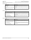
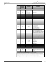
Relay Outputs
3310 8001 Relay Output Number ➀ Configures relay for external control.
3311 8001 Relay Output Number
➀ Configures relay for internal control.
3320 8001 Relay Output Number
➀ De-energizes designated relay.
3321 8001 Relay Output Number
➀ Energizes designated relay.
3330 8001 Relay Output Number
➀
Releases specified relay from latched
condition.
3340 8001 Relay Output Number
➀ Releases specified relay from override control.
3341 8001 Relay Output Number
➀ Places specified relay under override control.
3350 8001 9999 De-energizes all relays.
3351 8001 9999 Energizes all relays.
3361 8001 Relay Output Number
➀ Resets operation counter for specified relay.
3362 8001 Relay Output Number
➀ Resets the turn-on time for specified relay.
3363 8001 None Resets the operation counter for all relays.
3364 8001 None Resets the turn-on time for all relays.
3365 8001 Input Number
➀
Resets the operation counter for specified
input.
3366 8001 Input Number
➀ Resets turn-on time for specified input.
3367 8001 None Resets the operation counter for all inputs.
3368 8001 None Resets turn-on time for all inputs.
3369 8001 None Resets all counters and timers for all I/Os.
3370 8001 Analog Output Number
➀ Disables specified analog output.
3371 8001 Analog Output Number
➀ Enables specified analog output.
3380 8001 9999 Disables all analog outputs.
3381 8002 9999 Enables all analog outputs.
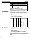
➀ You must write to register 8001 the number that identifies which output you would like to use. To determine
the identifying number, refer to“I/O Point Numbers” on page 86 for instructions.
➁ Data buffer location (register 8019) is the pointer to the first register where data will be stored. By default,
return data begins at register 8020, although you can use any of the registers from 8020–8149. Take care when
assigning pointers. Values may be corrupted if two commands are using the same register.
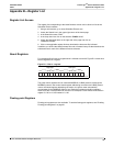
Refer to “Register List Access” on page 79 for instructions on accessing the complete register list.