


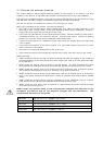
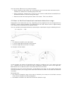

You can find the A-B line for any vessel as follows:
• Using a drawing of the vessel, lay a rule along the line of the main deck and continue this
forwards as a dashed line extending beyond the bow.
• Using a protractor, measure the θ° value (for your scanner model) below the dashed line at
the bow and draw in a new line along this angle.
• Extend the new line back beyond the bow of the vessel. This is the A-B line.
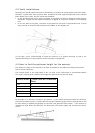
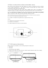
4.5 How to find the theoretical maximum detection range
Propagation of the radar beam can vary, depending on the properties of the air through which it's
traveling. Under normal conditions, the distance that the radar beam travels is approximately
10% further than the distance to the optical horizon.
You can calculate the theoretical distance traveled by the radar beam using the following formula:
D = 2.23 (√h1 + √h2)
where:
• D is distance traveled by the radar beam
• h1 is the height above sea level of the scanner
• h2 is the height above sea level of a target
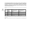
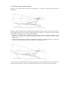
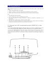
An example is shown below:
In this example, the scanner is installed on the vessel at a height of 10 ft (3 m) above sea level
(h1). Island A is 33 ft (10 m) high (h2) and for comparison, Island B is 16.4 ft (5 m) high (h2).
Both islands are at a distance (D) of 10 nautical miles from the vessel.
Calculations using the formula show that, at this distance, the radar can only detect objects that
are more than 25 ft (7.6 m) high, which means that Island A is shown on the radar but Island B is
not shown.
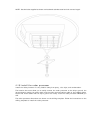
Remember that:
• the maximum detection range of the radar is limited by the curvature of the Earth's surface
under normal conditions of wave propagation.
• bad weather conditions can reduce the maximum detection range