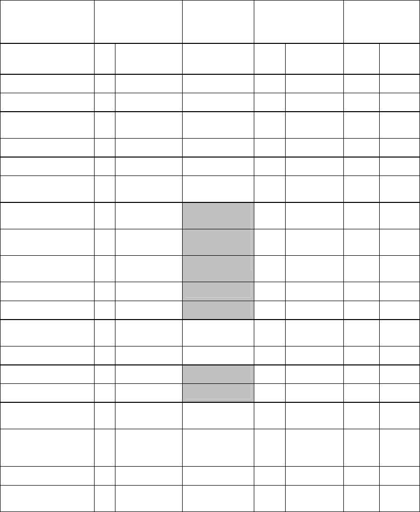
NMEA devices must be connected to an unused NMEA port on the connector strip.
The remote power signal configuration is explained in "Configure the remote power control for a
6000i or 6100i (common power source)" and "Configure the remote power control for a 6000i or
6100i (different power sources)".
Wire function
6000i/6100i
Connector PIN
Bare Wires
Radar Comms
(Connector 1)
SmartCraft
(Connector
2)
PI
N
Color Color Pin Color Pin Color
NMEA 1 IN A 3 Brown Brown
NMEA 1 IN B 1 Blue Blue
NMEA 1 IN
GROUND
4 White/Blue White/Blue
NMEA 1 OUT A 12 Violet Violet
NMEA 1 OUT B 7 Gray Gray
NMEA 1 OUT
GROUND
8 Blue/White Blue/White
NMEA 2 IN A 6 White/Brown
White/Brown
*
1 Green
NMEA 2 IN B 2 Brown/White
Brown/White
*
2 Red
NMEA 2 IN
GROUND
5 White White *
NMEA 2 OUT A 15 Yellow Yellow * 7 Orange
NMEA 2 OUT B 11 Orange Orange * 8 Blue
NMEA 2 OUT
GROUND
10 Black Black 12 Yellow
RS-232 GROUND 17 Tan Tan
1 White
RS-232 RX 16 Green Green **
3 Green
RS-232 TX 18 Red Red **
8 Red
REMOTE SAVE 13 Orange/Whit
e
Orange/White
6000i or 6100i
REMOTE POWER
OUT
14 Pink Pink
SHIELD 9 Drain Drain 9 Drain
RADAR REMOTE
POWER IN
White/Orang
e
10 Brown


