


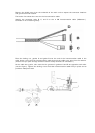
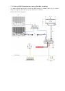
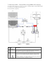

6.4 Connect the power cable
The power cable to the radar processor is NOT supplied. Power must be supplied through a
fuse/breaker element located at the power source end of the power cable.
Check the system specifications section for the recommended DC input voltage.
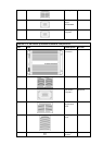
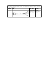
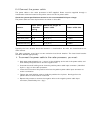
The power cable and fuse requirements are shown in the table.
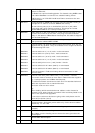
Scanner
Fuse/Circui
t breaker
rating
Maximum length of
power cable
Power cable size
2 kW 12 v DC
ONLY
5 A 33 ft (10 m) 14 AWG
4 kW 12-24 v DC 10 A 26 ft (8 m) 14 AWG
6 kW 12-24 v DC 10 A 26 ft (8 m) 14 AWG
10 kW 24v DC only 15 A 26 ft (8 m) 12 AWG
25 kW 24v DC only 15 A 26 ft (8 m) 12 AWG
Typically the fuse /breaker would be located in a fuse/breaker box with the fuses/breakers for
other devices.
The radar processor must have it's own exclusive fuse/circuit breaker. The fuse/circuit breaker
should be labeled appropriately.
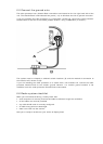
¾ To connect the power cable to the radar processor, you must:
• Strip away approximately 0.4" (10 mm) of the shielding at the end of the power cable, and
then identify the positive wire and the negative wire.
• Unscrew the small holding screw from the positive power cable input connector (identified
by the + sign) on the radar processor.
• Insert the bare ends of the positive wire into the positive power cable input connector to
make a connection.
• Tighten the small holding screw to hold the positive wire in place. Gently pull on the
positive wire to ensure that it is secured.
• Repeat this process to connect the negative wire to the negative power cable input
connector (identified by the – sign).