


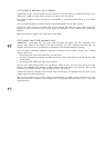
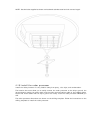
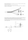
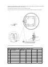
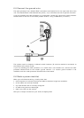
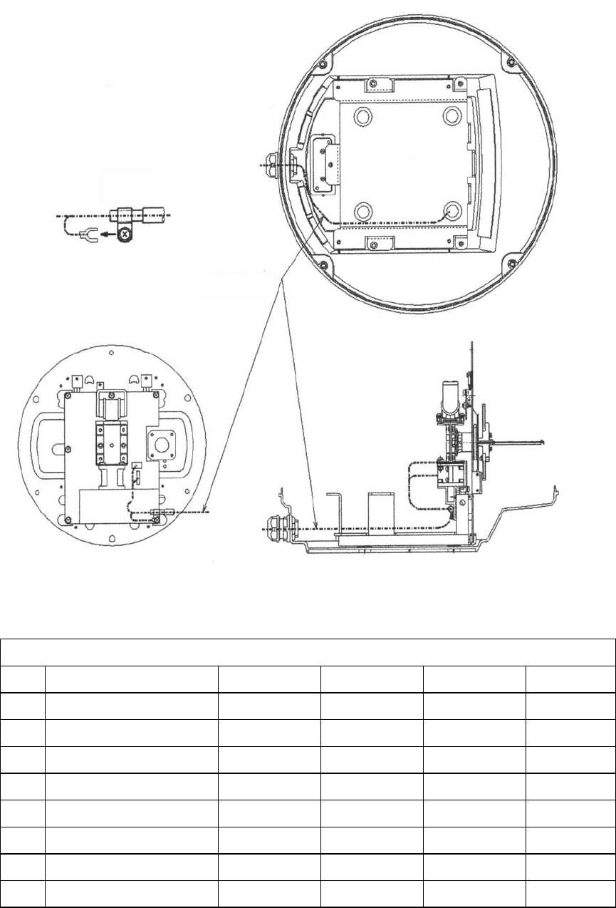
Place the internal locking nut over the end of the interconnection cable, then attach connectors B
and C to the connectors (as shown in the figure).
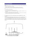
The broken line shows the route for the interconnection cable.
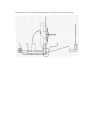
Attach connector D to one of the screws close by to provide an Earth (as shown in the figure).
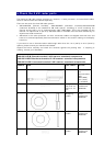
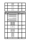
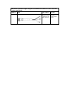
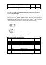
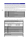
The wiring details for the connector ends (B, C, and D) are as follows:
2 kW interconnection cable (NS003101) connector ends
Pin Color/Name AWG size B C D
1 Green (big) #12
1
2 Yellow (big) #12
2
3 Green (thin) #24 7
4 Clear Coax signal #24 4
5 Drain wire for 4 #24 5
6 Drain wire for 7 #24 3
7 Black Coax signal #24 2
8 White #24 6