


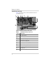


Installing the HI400
18
5. Connect the black and white (line and neutral) wires from
the AC cable to the black and white wires located in the
HI400 hardwire compartment. Be sure to connect black
to black and white to white. Check to make sure the wires
are making a good connection, and secure the twist-on
wire connectors with electrical tape.
6. Connect the ground wire (bare or green) from the AC
cable to the green-headed screw on the back wall of the
hardwire compartment. Use a crimp-on ring terminal if
the AC input ground wire is stranded. Solid wire can be
secured directly under the head of the screw.
7. Connect the load end of the AC cable to your system’s
AC output circuit breaker, or the load distribution panel
depending on your system design.
Installing the ignition lockout wiring
The ignition lockout system turns the inverter off when the
ignition is on. The system is designed so that when a user-
applied 12 V signal is present on the red ignition lockout wire
in the hardwire compartment, the inverter turns off. This 12 V
signal is normally obtained by connecting a wire to circuits
downstream from the vehicle ignition switch, so that 12 V is
present when the ignition is on, and not present when the
ignition is off. The circuit selected should be protected by a
fuse rated maximum 5 Adc.
To install the ignition lockout wiring:
1. Connect a min. No. 18 AWG wire to an appropriate,
fused 12 V ignition-switched circuit. In the following,
this wire is referred to as the “lockout signal wire.”
WARNING: Shock hazard, risk of damage
Do not connect the HI400 Inverter output to AC
distribution wiring powered by any other source. Shock
hazard and damage may result.