


10
Installation and Set-Up
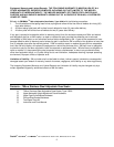
Receiving And Handling
After the machine has been uncrated, examine the
case sealer for damage that might have occurred
during transit. If damage is evident, file a damage
claim immediately with the transportation company
and also notify your 3M Representative.
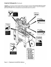
PACKAGING AND SEPARATE PARTS
1. Remove straps and staples and lift fiberboard
cover off pallet.
2. Remove protective wrapping around machine.
3. Cut and remove cable tie from electrical conduit.
4. Cut cable ties that secure upper assembly to
machine bed on each side.
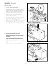
5. Remove tape drum bracket bolts (4) from top
crossbar and install tape drum bracket from
parts box as shown in Figure 2-1A.
Machine Set-Up
Note – A tool kit consisting of metric open end
and hex socket wrenches is provided with the
machine. These tools should be adequate to set-
up the machine, however, other tools supplied by
the customer will be required for machine
maintenance.
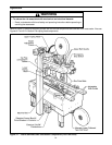
The following instructions are presented in the order
recommended for setting up and installing the case
sealer, as well as for learning the operating
functions and adjustments. Following them step by
step will result in your thorough understanding of the
machine and an installation in your production line
that best utilizes the many features built into the case
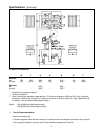
sealer. Refer to Figure 3-1 to identify the various
components of the case sealer.
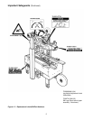
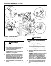
6. Loosen and move both compression rollers out
so they don't catch on side guides.
7. Install height adjustment crank and locking knob
on top of left column as shown in
Figure 2-1B. Crank upper assembly up high
enough to allow clear access to lower taping
head. Remove and discard the two cushion
shipping blocks.
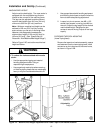
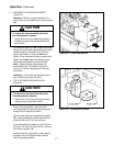
8. Using 17 mm wrench, remove nuts from top of
side guides. Replace with black knobs from
parts box. Figure 2-1C.
9. Cut and remove cable ties on both upper and
lower taping heads. (Applying/buffing rollers are
held retracted for shipment.)
Hold taping head BUFFING ROLLER and cut
and remove cable tie that holds applying/
buffing arms retracted. See Figure 2-1D.
Allow buffing/applying arms to extend slowly.
10. Install machine stops onto columns as shown in
Figure 2-1E. Use the lowest hole position and
bolt into the lowest threaded insert on the
column.
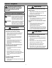
• To reduce the risk associated with
mechanical and electrical hazards:
− Read, understand and follow all safety and
operating instructions before operating or
servicing the case sealer
WARNING
• To reduce the risk associated with sharp
blade hazards:
− Keep hands and fingers away from tape cutoff
blades under orange blade guards. The
blades are extremely sharp
WARNING