


27
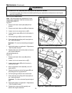
Special Set-Up Procedure (Continued)
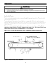
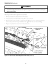
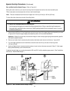
Box and Machine Bed Height Range – Refer to Figure 6-4
Moving the outer columns up one set of mounting holed increases the maximum box size handled by the
700a-s case sealer and decreases the minimum machine bed height.
Note – This also increases the minimum box height from 120 mm [4.8 inch] to 165 mm [6.5 inch].
To move the outer columns up one set of mounting holes:
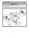
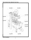
1. Place minimum 305 mm [12 inch] high blocks at the front and rear of the upper taping head assembly as shown
in Figure 6-4A. Crank the upper taping head assembly down until it touches these blocks.
Important – Blocks (front and rear) must be same height in order to keep upper taping head assembly parallel
with machine bed/drive belts.
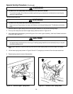
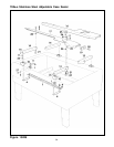
2. Remove and retain the six screws and plain washers that fasten each column to the frame. Figure 6-4B.
3. Turn the height adjustment crank clockwise to raise the outer columns up one set of mounting holes
(100 mm [4 inch]).
4. Install and tighten the six screws and plain washers in each column that were removed in Step 2. Crank upper
taping head assembly up and remove blocks.
If desired, the bed height can now be decreased to 520 mm [20.5 inch] by adjusting legs upward. (See "Installation
and Set-Up – Machine Bed Height".)
Figure 6-4 – Box and Machine Bed Height Range
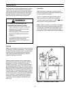
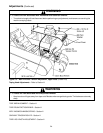
• To reduce the risk associated with muscle strain:
− Use the appropriate rigging and material handling equipment when lifting or repositioning this equipment
− Use proper body mechanics when removing or installing taping heads that are moderately heavy or may be
considered awkward to lift
WARNING