


17
Operation (Continued)
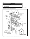
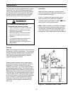
Note – Upper head has unique feature for
overstuffed boxes. The head will raise up to
13 mm [1/2 inch] to compensate for this type
of condition.
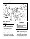
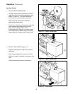
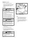
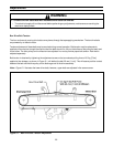
3. RUN BOXES TO CHECK ADJUSTMENT
(Figure 3-5)
Turn electrical switch to "On" to start drive belts.
Move box forward under upper taping head until it
is taken away by drive belts. If box is hard to
move under head or is crushed, raise head
slightly. If box movement is jerky or stops under
upper head, lower upper head slightly to add
more pressure between box and drive belts.
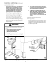
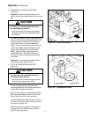
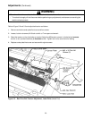
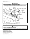
4. TOP FLAP COMPRESSION ROLLERS
(Figure 3-6)
The top flap compression rollers have two
mounting positions to provide side compression
through the full range of box widths.
The rollers have been pre-assembled in position
"B" to accommodate box widths from 200 mm
[8 inch] to 545 mm [21.5 inch] maximum.
To accommodate box widths less than 200 mm
[8 inch] to 140 mm [5.5 inch] minimum, move all
four rollers to position "A".
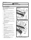
Adjust the top flap compression rollers against
top edge of box and tighten knobs to secure
rollers in operating position.
Important – Before turning drive belts on, be
sure no tools or other objects are on the conveyor
bed.
Important – If drive belts are allowed to slip on
box, excessive belt wear will occur.
Figure 3-6 – Compression Rollers
Figure 3-5 – Check Adjustments
• To reduce the risk associated with pinch
and entanglement hazards:
− Keep hands clear of the upper head support
assembly as boxes are transported through
the machine
CAUTION
• To reduce the risk associated with pinch
and entanglement hazards:
− Keep hands, hair, loose clothing and jewelry
away from box compression rollers.
CAUTION