


11
Installation and Set-Up (Continued)
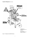
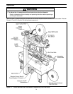
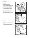
Push buffing roller into head to check for free,
smooth action of taping heads.
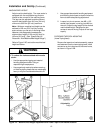
12. Ensure that the tape drum bracket assembly,
located on the lower taping head, is mounted
straight down, as shown in Figure 2-2A. The
tape drum bracket assembly can be pivoted to
provide tape roll clearance in certain cases.
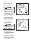
13. Remove fasteners that secure case sealer legs
to pallet.
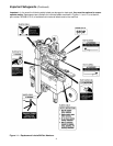
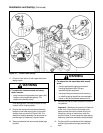
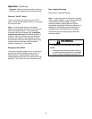
11. Check for free action of both upper and lower
taping heads.
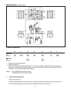
Figure 2-1 – 700a-s Frame Set-Up
14. Remove the machine from the pallet and move it
into position.
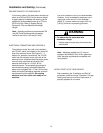
Important – Whenever the machine is lifted with
a fork truck, insure that the forks span com-
pletely across the machine frame and do not
contact any wiring or mechanism under the
machine frame. In some cases the lower taping
head may need to be removed to avoid damage.
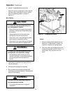
15. Continue with the remainder of the Installation
and Set-Up procedure through the end of the
topic.
• To reduce the risk associated with sharp
blade hazards:
− Keep hands and fingers away from tape cutoff
blades under orange blade guards. The
blades are extremely sharp
WARNING
• To reduce the risk associated with muscle
strain:
− Use the appropriate rigging and material
handling equipment when lifting or
repositioning this equipment
− Use proper body mechanics when removing
or installing taping heads that are moderately
heavy or may be considered awkward to lift
WARNING