


"UniVert 2" inverter
Page 14 of 42 8000012364 BAL, en
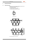
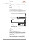
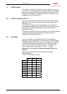
Figure 2 illustrates the principle of an INV.
In normal operation, the load is supplied "Online" by the INV. With
systems comprising several parallel INVs, the load current is divided
in accordance with the number of INVs. Depending on the system
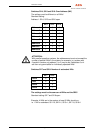
design, a power supply using up to 8 INVs can be realised. In addition
to the parallel operation of several INVs, the reliability of supply can
be further increased by integrating a static bypass switch, SBS. In the
event of a failure of several INVs, switchover to the mains takes place
without any interruption. Apart from power cabling, a bus line is
required for control purposes between the units for systems
comprising several INVs (and SBSs). The bus line has to be
terminated at both ends with a resistor.
ATTENTION:
This INV must not be connected in parallel to the mains on the output
side!
2.4 Principle of Operation of the INV, Electrical
After connection of the DC voltage, the DC filter capacitors are
charged via the softstart device. The control unit activates a bridging
contactor as soon as the capacitor charging process is finished. The
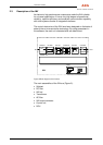
DOU displays measured values (output voltage/output current) on the
LCD and the unit status via LEDs. The INV is switched on using the
ON/OFF switch on the DOU. When the INV has been switched on, it
can be started or stopped by connecting or disconnecting the
DC voltage supply.
The transistor INV set, pulsed with approx. 20 kHz, transforms the
direct voltage into a single-phase sinusoidal AC voltage. The voltage
is transformed electrically isolated to the required AC output voltage
using a transformer. The secondary voltage is led to the load
terminals via the AC filter, a miniature circuit-breaker, a current
transformer and the INV output contactor. The stabilised output
voltage of the INV is short-circuit-proof and can supply loads from
capacitive through ohmic to inductive, as well a non-linear loads with
a high crest factor. The INV also supplies high starting currents for
motor loads. Refer to chapter "Technical data" for the exact
specifications. The entire control and monitoring process is carried
out using a microprocessor. LEDs and relays show the unit status,
whilst output voltage and output current are displayed on an LCD.
INVs for parallel operation need a choke between the INV output and
the busbar. When several INVs are operated in parallel, or one or
more INVs are operated with an SBS, a CAN bus is required between
the units for control purposes. An additional CAN bus allows the unit
to be integrated in a power supply system and connected to a central
control and monitoring unit (PSM).
With individual units, the INV immediately starts after actuating the
ON/OFF switch. With an INV with SBS and presence of the mains,
the INV starts immediately, but the output contactor is only switched
on after synchronisation with the mains. With systems comprising
several INVs, these synchronise to the mains and then jointly switch
on the output contactor. The INV can be switched off in every
operating status without delay using the ON/OFF switch.