


"UniVert 2" inverter
Page 20 of 42 8000012364 BAL, en
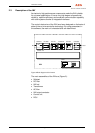
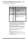
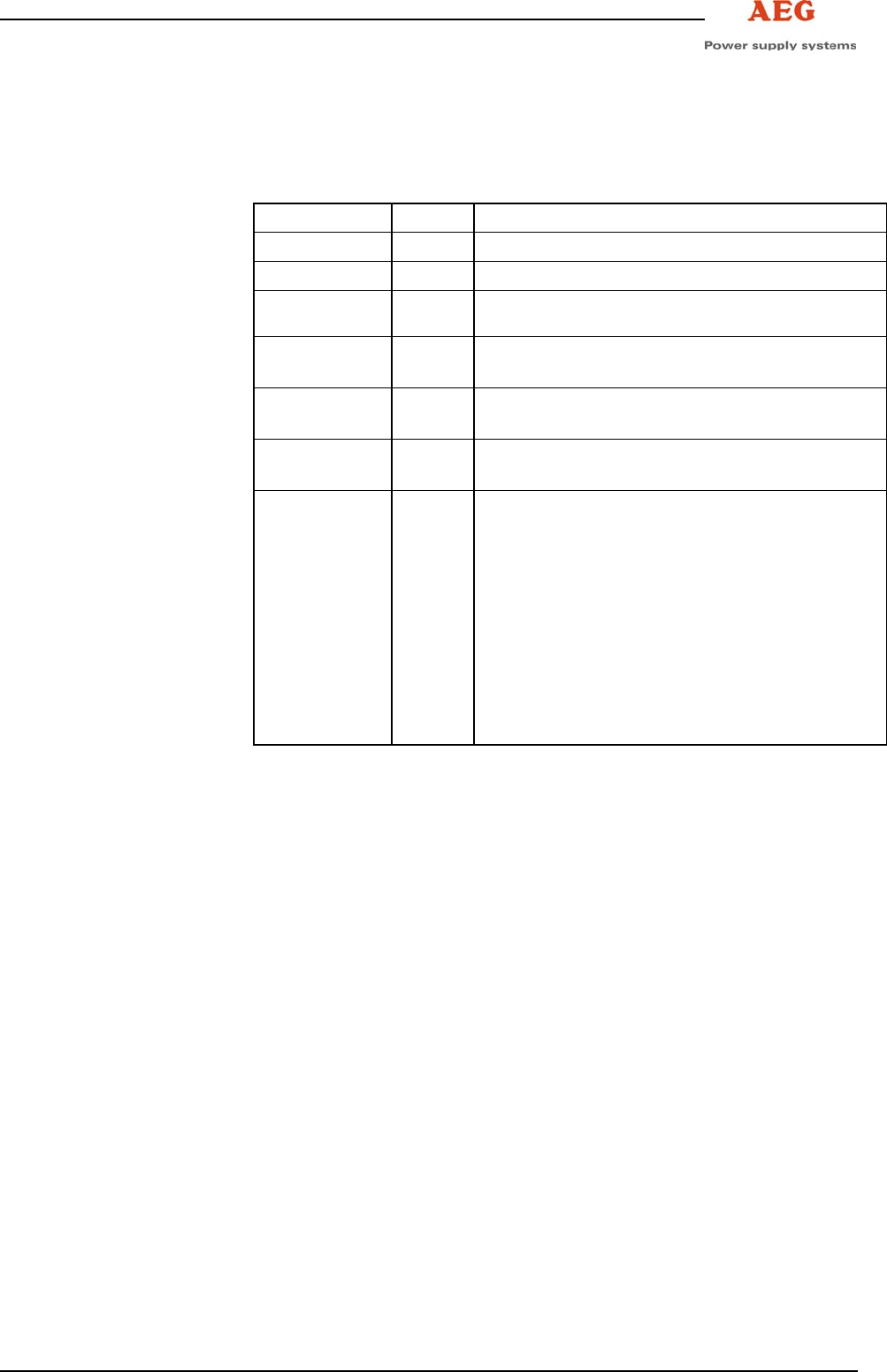
3.10 Signalling, Displays and Remote Signals
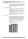
The following signals are indicated via LEDs on the front panel:
Display Colour Operating status
Operation green INV operation
U
O
OK green INV output voltage present
U
I
< red Input voltage < 85% of rated voltage,
INV has switched off
U
I
> red Input voltage > 128% of rated voltage,
INV has switched off
Fault red INV output voltage below 90% of rated
voltage
ϑ>
red Overtemperature on heat sink or
overload
Collective
fault
red Delayed collective fault signal,
delay time 20 s,
signalling relay is triggered at the same time.
The following disturbing influences are
registered:
INV fault
U
I
<
U
I
>
ϑ>
Overload
INV output miniature circuit-breaker
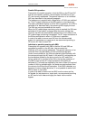
The unit is equipped with a liquid-crystal display. When the unit is
switched off, the LCD shows "OFF", when the unit is switched on it
shows the INV output voltage and output current. While the INV starts
up and output contactor K7 is still switched off, "READY" is signalled.
In the event of a fault, the 1
st
display row shows "FAULT" and the
2
nd
display row shows the type of fault.
The INV voltage and current values are displayed with three decimals
before and one decimal after the decimal point. The display accuracy
corresponds to class 1 with respect to the rated output value of the
unit.
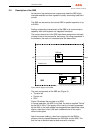
Remote signalling is carried out by means of potential-free contacts
via a Combicon connector on the front of the unit.
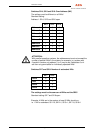
Assignment of the signal terminals:
INV fault:
In the event of a signal, X10.2 – X10.3 or X3.2 – X3.3 close.
No fault: X10.2 – X10.1 or X3.2 – X3.1.
When the INV is disconnected from the power supply (no DC supply),
a fault is signalled!
The remote signals are designed for safe isolation. The minimum load
should not be below 12 V and 0.1 A.