


"UniVert 2" inverter
Page 18 of 42 8000012364 BAL, en
3.7 ON/OFF Switch
The inverter is set ready for operation using the DOU switch on the
front panel. The monitoring functions with their respective messages
are only active when the inverter is switched on. After switch-off, all
faults are acknowledged. The settings of the DIL switches are only
accepted if the unit is switched off!
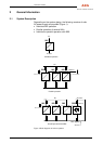
3.8 CAN Bus Interfaces X6 / X7
The unit can be controlled and monitored using the 10-pin CAN bus
connector X6 if the INV is installed in a power supply cabinet with
PSM control unit.
The CAN bus connector X7 has no significance if one inverter in
single operation operated without SBS. Both ends of the bus have to
be connected to a terminating resistor when several INVs are
operated in parallel!
For operation with SBS, only the end of the bus on the INV must have
a terminating resistor connected; a bus terminating resistor is
integrated in the SBS! (See Figure 1.)
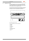
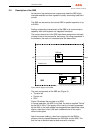
3.9 DIL Switch
An 8-pin DIL switch is arranged below the LCD. All settings of /
changes to the DIL switch are only activated after the INV has been
switched off using the ON/OFF switch. It is counted from the left S2.1
to the right S2.8, switches that are pushed in at the bottom signify
"open"! The setting of the switches is shown on the display as a
check whenever a change is made; 0 = open; 1 = closed.
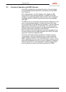
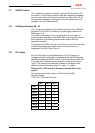
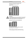
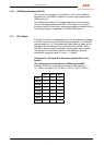
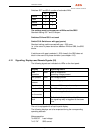
Switches S2.1, S2.2 and S2.3: Number of parallel INVs in the
system
The settings must be the same on all INVs and the SBS!
Standard setting:
1 INV: S2.1, S2.2 and S2.3 open
S2.1 S2.2 S2.3
1 INV
0 0 0
2 INVs
0 0 1
3 INVs
0 1 0
4 INVs
0 1 1
5 INVs
1 0 0
6 INVs
1 0 1
7 INVs
1 1 0
8 INVs
1 1 1