


"UniVert 2" inverter
Page 15 of 42 8000012364 BAL, en
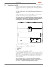
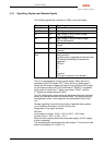
2.5 Description of the SBS
Its electronic high-performance components make the SBS highly
overload-resistant and thus capable of quickly eliminating load short
circuits.
The SBS can be used as the central SBS for parallel operation of up
to 8 INVs.
Another outstanding characteristic of the SBS is its communication
capability with other systems via integrated interfaces.
The control electronics of the SBS have been designed on the basis
of state-of-the-art microcontroller technology. By using parameters in
the software, the main unit characteristics are determined.
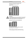
SBS set
Control unit
A
C Load
SBS
DOU
U = 231V
I = 10.3A
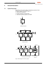
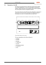
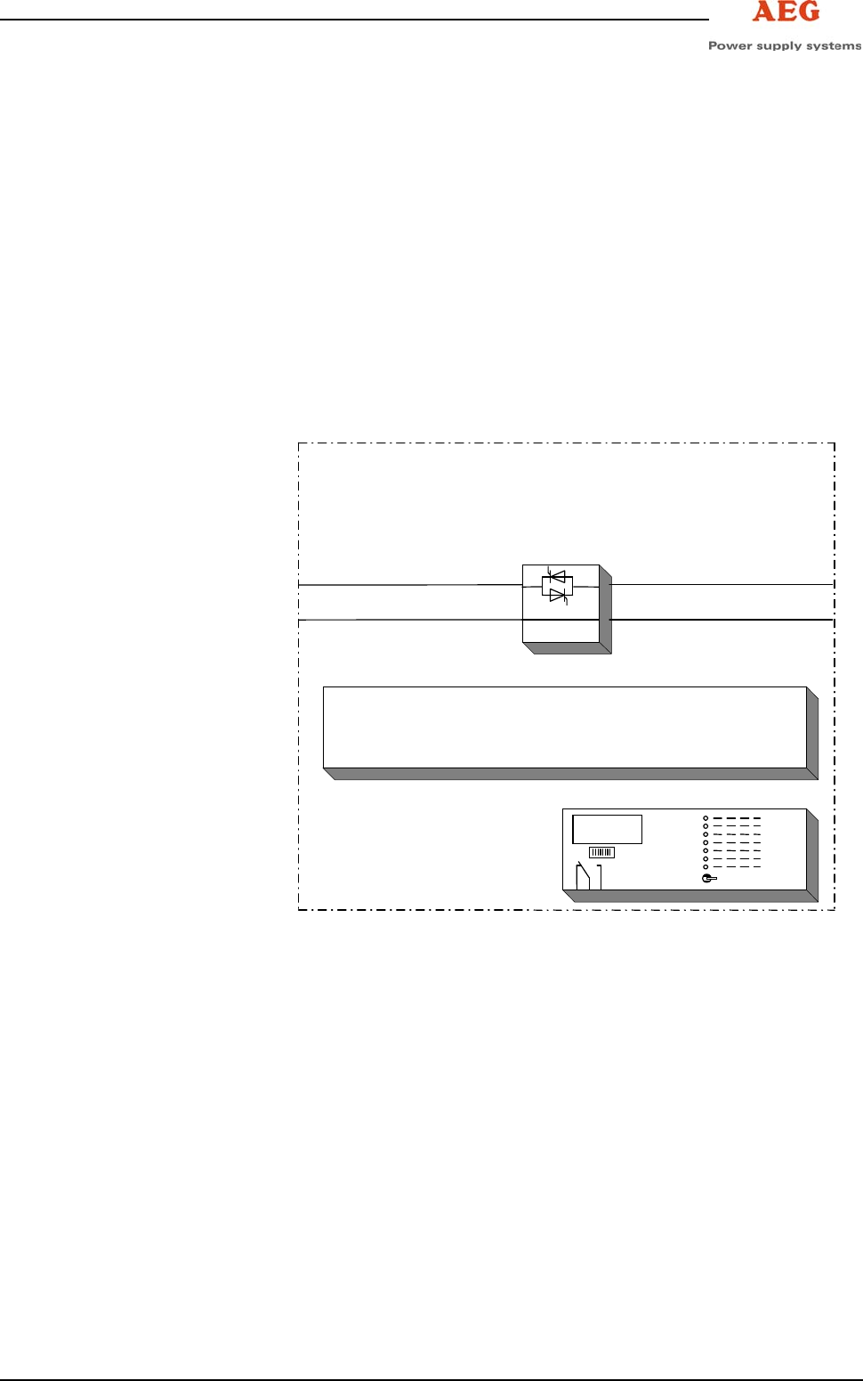
Figure 3 Block diagram of the SBS
The main components of the SBS are (Figure 3):
• Thyristor set
• Control unit
• DOU
Figure 3 illustrates the principle of an SBS.
In normal operation, the SBS is not fired, the load is supplied "Online"
by the INV or INVs. If the supply of the load is no longer guaranteed
by the INVs or the load voltage has dropped below a permitted value
due to a load short circuit, the load is switched over to the mains
without interruption.
Apart from power cabling, a bus line is required for the SBS for
process control purposes between the INV/INVs and the SBS. The
bus line has to be terminated at both ends with a resistor.