


Chapter 3: Installation
724-746-5500 | blackbox.com
15
3. Installation
Make sure you have everything listed in Chapter 2, Section 2.6 for your 1101 or 1102 Secure Device Server.
3.1 Power Connection
The LES1101A or LES1102A models are each supplied with an external DC wall mount power supply. This power supply comes with a selection of
wall socket adapters for each geographic region (North American, Europe, UK, Japan or Australia) and will operate with 100-240 VAC, 50/60 Hz
input, 7.2 watts maximum.
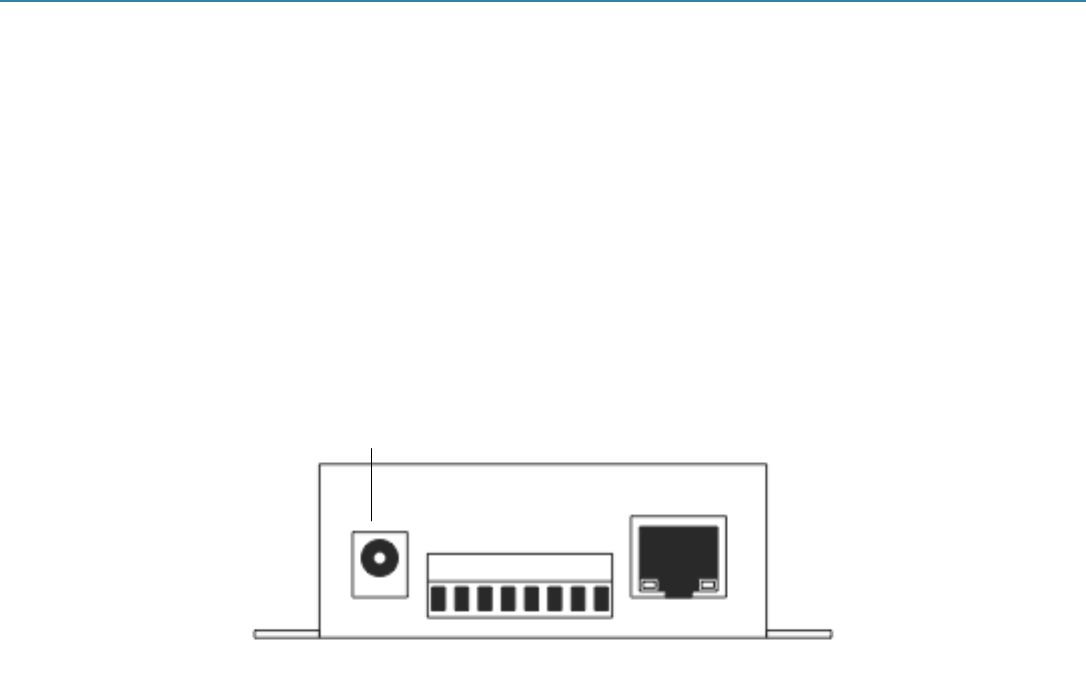
Plug in the DC power cable. The 12V DC connector from the power supply unit plugs into the DC power socket on the side of the console server
casing.
Plug in the power supply AC power cable and turn on the AC power. Confirm that the console server Power LED (PWR) is lit.
NOTE: When you first apply power to the LES1101A or LES1102A the Local and Serial LEDs will flash alternately.
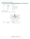
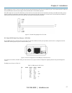
The LES1102A can also be powered directly from any +9V DC to +48V DC power source by connecting the DC power lines to the IN-GND and
VIN+ screw jacks.
Power connector
Figure 3-1. Power connector.
3.2 Network Connection
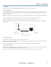
The RJ-45 LAN ports are located on the side of the LES1101A and LES1102A units.
All physical connections are made using industry standard CAT5 cabling and connectors. Make sure you only connect the LAN port to an Ethernet
network that supports 10BASE-T/100BASE-T.
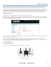
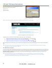
The first time you configure the console server, you must connect a PC or workstation to the console server’s network port.
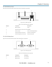
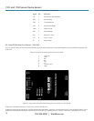
3.3 Serial Port Connection
The LES1102A has two DB9 serial ports (Ports 1–2). By default, Port 1 is configured in Local Console (modem) mode. The LES1101A also has one
DB9 serial port that‘s configured by default in Local Console (modem) mode.
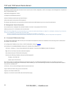
The serial ports are all set by default in RS-232 mode. The RS-232 pinout standards for the DB9 connector are described in Table 3-1.
+9 to +48 VDC 1 GND