


Chapter 3: Installation
724-746-5500 | blackbox.com
17
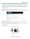
Web management console. Two short cable loops are also required between the RX+/TX+ pins and RX-/TX- pins. This is because the LES1102A uses
universal differential transceivers that support 4-wire (RS-422) and 2-wire (RS-485) operation.
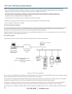
In RS-485 mode, Port 2 on the LES1102A listens on the 2-wire bus for receive data until it is required to send data. In RS-485 send mode, it stops
receiving, enables its transmitters when there is data to be sent, transmits the data, and returns to receive mode. This eliminates the possibility of
collisions with other devices that share the RS-485 bus and avoids receiving stale echoed data.
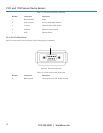
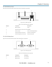
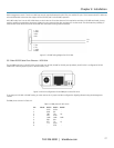
Figure 3-3. RS-485 wiring diagram for LES1102A.
3.3.2 Non RS-232 Serial Port Pinouts— LES1101A
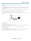
The one DB9 serial port on the LES1101A can be used as an RS-232, RS-485 or RS-422 port. By default, the LES1101A is configured in RS-232
mode (with a vertical jumper in place on the left hand J1 pins).
Figure 3-4. RS-232 configuration for the DB9 port on the LES1101A.
To set the port in RS-422 or RS-485 mode, you must remove the J1 jumper and then configure the Signaling Protocol using the Management
Console.
The DB9 pinout is shown in Table 3-3.
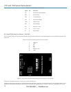
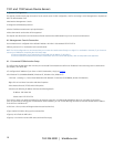
Table 3-3. DB9 pinout for LES1101A.
Pin: Mode: RS232 RS422 RS485
1 DCD DCD+ -
2 RXD RX - -
3 TXD TX + D+
4 DTR DTR+ -
5 GND GND GND
6 DSR RX + -
7 RTS TX - D-
8 CTS DCD- -
9 - DTR- -
D+
D-
1 +3V
2 GND
3 RX+
4 RX-
5 TX+
6 TX-
7 +VIN
8 GND