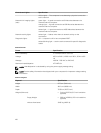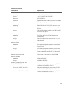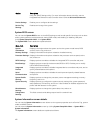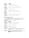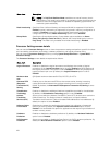
Internal connectors Specification
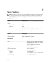
Internal USB One 4-pin, USB 3.0-compliant
System power one 24-pin connector
Power distribution board communication one six-pin connector
Front panel control one 28-pin connector
Systems fans six four-pin connectors
Host card remote power control one two-pin connector
CPU/Memory power four four-pin connectors
Memory twenty four 240-pin connectors (DDR4)
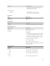
Risers:
Riser 1
PCI Express three 164-pin connectors (x8)
Center Riser Option 3: Default
PCI Express two 164 pin connectors (x8)
Left Riser
PCI Express one 164 pin or two 164 pin
Front IO:
Front USB one 14-pin connector
Front panel control one 28-pin connector
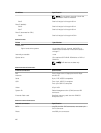
HDD Back Panel :
SATA two 36-pin Mini-SAS connectors; eight 29-pin
HDD connectors
Power one 14–pin connector
Table 15. Controls and Lights
Controls and Lights Specification
Power button light: off — system is off or unplugged.
solid blue light — computer is operating normally.
blinking blue light — computer is in stand by.
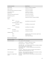
solid amber light — the computer does not start, indicating a problem
with the system board or power supply.
blinking amber light — indicates a problem has occurred with the
system board.
System ID button and light blue light — flashes (front and back of chassis) when the button is
pressed. Press the button again to turn it off.
Drive activity light blue light — blinking blue light indicates that the computer is reading
data from, or writing data to the hard drive.
Network link integrity lights
(front):
blue light — A good connection exists between the network and the
computer.
117


